Toyota Prius Gen 2 Inverter Controller

Topics concerning the Toyota and Lexus inverter drop in boards
MattsAwesomeStuff
Posts: 898
Joined: Fri Apr 26, 2019 5:40 pm
Has thanked: 291 times
Been thanked: 177 times

Re: Toyota Prius Gen 2 Inverter Controller

Post by MattsAwesomeStuff »

MattsAwesomeStuff wrote: Mon Apr 17, 2023 12:38 pmWell crap, so, just powering up the inverter itself... fried.
Well... awful news.

I've been getting a ton done on my car. Working on mounting the Bosch iBooster and other mechanical things.

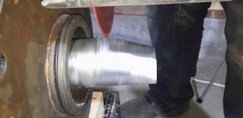
It was time to make progress on the driveline again. So I took the day off, helped a friend empty their garage for me to use, packed up lots of my tools and my motor and inverter and two car batteries and battery chargers and basically a whole mobile shop for me to spend the day using the motor as a lathe to machine the other half of my motor coupler and where it connects to the transmission output shaft. My goal by the end of the day was to have the powertrain ready to install into the car and see the tires spin.

...

Wire it all up, connect it up, motor's not spinning.

Check and double check, try again, motor's not spinning.

But the 12v system wires are warm again. Tested the voltage, 8v. Disconnected power to the inverter, jumps back to 12v.

ANOTHER INVERTER FRIED?

Was only pulling 1.6 amps (1.4 is normal), but otherwise same symptoms as the last time my inverter fried.

I don't have any more spare inverters, and they very, very rarely appear at a junkyard (took me 4 years to get the 2 I have).

One fried inverter is coincidence. Two fried inverters means... either the board or me is doing something to fry them. Toyota inverters at that.

Anyone have any ideas what could be causing the inverter to power hog or short internally like this? Or what I could do to find out?

Only thing I can think of that I maybe did wrong, was not use a pre-charge resistor when connecting the "HV" power (12v or 24v today). Doesn't explain to me why the system 12v is shorted.
MattsAwesomeStuff
Posts: 898
Joined: Fri Apr 26, 2019 5:40 pm
Has thanked: 291 times
Been thanked: 177 times

Re: Toyota Prius Gen 2 Inverter Controller

Post by MattsAwesomeStuff »

Oh boy, the most fun of errors. Intermittent and non=reproduceable ones. Went back and tried again, it worked. *shrugs* Until, presumably, some time later again, it won't.

I also discovered that grinding zinc is like grinding aluminum. It fills up your grinding or cutting wheel with molten zinc, and then there's no friction to cut, and the disc is ruined, and you got 1/8" past the surface. Plan B is using a circular saw, because grinding against a lathe wasn't janky enough...
Pete9008
Posts: 1801
Joined: Sun Apr 03, 2022 1:57 pm
Has thanked: 102 times
Been thanked: 347 times

Re: Toyota Prius Gen 2 Inverter Controller

Post by Pete9008 »

Glad it's come back to life!

Still think it might be that the 12V power supply you are using is struggling to cope with the power up surge (boths its own surge and the inverter surge simultaneously). If the inverter gets into that low voltage, not quite powering up properly mode, then it's likely that some bits of the inverter power supply will be getting stinking hot. If it's not on for too long they will probably survive but if left for a while could well end up permanently damaged. If it is that then something as simple as adding a switch in the 12V line could fix it, power the 12V PSU up first and then flip the switch to bring the inverter supply up. It means the power supply isn't powering up into the load and when you flip the witch it's reservoir caps are fully charged to help supply the inverter's power on surge.

I'd strongly suggest that you resist the temptation to use a circular saw. :shock: (hopefully you're joking!)

Seem to remember that you can get grinder disks specifically for aluminium (although never tried one), wonder if they might work better on the zinc?
Jacobsmess
Posts: 488
Joined: Thu Mar 02, 2023 1:30 pm
Location: Uk
Has thanked: 252 times
Been thanked: 62 times

Re: Toyota Prius Gen 2 Inverter Controller

Post by Jacobsmess »

I'm looking at options for my EV conversion and wondering if there are any reasons for/against particular inverters? My local scrapyard has a Prius inverter (not sure which year) for £100, is this a reasonable amount? It powers up, I'll likely pair it with the OI control board, I'm aiming to keep things as cheap as possible and investigating using either a leaf or Lexus motor. I don't know much about the Prius inverters but they seem popular and very cheap when compared to other options.
MattsAwesomeStuff
Posts: 898
Joined: Fri Apr 26, 2019 5:40 pm
Has thanked: 291 times
Been thanked: 177 times

Re: Toyota Prius Gen 2 Inverter Controller

Post by MattsAwesomeStuff »

Pete9008 wrote: Mon May 01, 2023 7:29 pmI'd strongly suggest that you resist the temptation to use a circular saw. :shock: (hopefully you're joking!)
Image

It worked great, especially dicing it up to get the general shape before using it like a lathe. Just a little scary at first when the high side was 10mm higher than the low spots. Had to feather it in quite a bit. Ended up only doing about 50% of it that way, and a more traditional (y'know, traditional way to make motor couplers from cast zamak) wood turning techniques.

Image

In other news, not sure how related the Sine algorithm is to whatever happens when I set the two testing variables (fslipspt and ampnom). For example, it seems to really struggle to hit some RPMs without jacking up the ampnom (huge difference between 55 and 60, and 60 and 70). And it seems to struggle to maintain some specific speeds, like the motor is fighting itself. Motor wires will sometimes get scalding hot even under no load.

Knowing my target was 400hz (highway speed), over the last couple weeks I was gradually cranking up the RPM a few every day, chickenfooting it running that fast. Got as high as 100hz yesterday before I stopped and did some math.

I'd thought 400hz was my high way speed. I'd announced such, I'd discussed whether it was achievable, etc. ... It's obviously wrong.

Tire circumference is roughly 2m.

That's 500 revolutions to a km.

100km/hour is 50,000 revolutions per hour.

3600 seconds in an hour = 13.9 tire Hz.

Final drive is 3.44, and stock 4th gear was 1:1 (not that I'm using the transmission), so 48 hz is enough for highway speed. Motor spec says 50hz, so, right where it should be. So that's all a big sigh of relief.
Pete9008
Posts: 1801
Joined: Sun Apr 03, 2022 1:57 pm
Has thanked: 102 times
Been thanked: 347 times

Re: Toyota Prius Gen 2 Inverter Controller

Post by Pete9008 »

Glad it worked (and that you still have a full compliment of legs ;) ) but :shock:

Like the lathe idea!

Erm, I may have missed something but how many poles does your motor have?
MattsAwesomeStuff
Posts: 898
Joined: Fri Apr 26, 2019 5:40 pm
Has thanked: 291 times
Been thanked: 177 times

Re: Toyota Prius Gen 2 Inverter Controller

Post by MattsAwesomeStuff »

Pete9008 wrote: Fri May 19, 2023 7:13 amErm, I may have missed something but how many poles does your motor have?
As I recall, it's a 6-200, which means 6. The link to the manufacturer has net-rotted.
Pete9008
Posts: 1801
Joined: Sun Apr 03, 2022 1:57 pm
Has thanked: 102 times
Been thanked: 347 times

Re: Toyota Prius Gen 2 Inverter Controller

Post by Pete9008 »

So doesn't that mean that you need 48x6 Hz (if that's 6 pole pairs or 48x3Hz if it's poles) ??
MattsAwesomeStuff
Posts: 898
Joined: Fri Apr 26, 2019 5:40 pm
Has thanked: 291 times
Been thanked: 177 times

Re: Toyota Prius Gen 2 Inverter Controller

Post by MattsAwesomeStuff »

Pete9008 wrote: Fri May 19, 2023 6:12 pm So doesn't that mean that you need 48x6 Hz (if that's 6 pole pairs or 48x3Hz if it's poles) ??
...

I dunno, does it? I had no idea that played into it. I have almost no understanding of what goes on inside the motor or software.

When I set the fslpspnt to 48hz, what speed is the shaft actually spinning? (presuming it's not slipping...).

I suppose acoustically, if I was actually spinning that shaft at 60hz with a high spot, when I put the chisel against it, it should've sounded like power grid humming rather than rapid ticking. It sounded still like rapid ticking.

Mine IIRC is the 180/6-200, which someone once said likely all the 6- motors were 6 pole, and 4- were 4 pole.

Image
Pete9008
Posts: 1801
Joined: Sun Apr 03, 2022 1:57 pm
Has thanked: 102 times
Been thanked: 347 times

Re: Toyota Prius Gen 2 Inverter Controller

Post by Pete9008 »

That looks like 6 poles or 3 pole pairs so you should need 150Hz electrical to get 50Hz shaft speed (3000rpm).

In the table 50Hz gives 970rpm, 3pole pairs at 50Hz actually works out to (50/3)x60=1000rpm. The difference is the slip.

Edit - no idea what fslpspnt does though or how it relates to electrical speed on the output (if running without an encoder then I'd guess it's the electrical output speed?).
MattsAwesomeStuff
Posts: 898
Joined: Fri Apr 26, 2019 5:40 pm
Has thanked: 291 times
Been thanked: 177 times

Re: Toyota Prius Gen 2 Inverter Controller

Post by MattsAwesomeStuff »

Long time no bump...

Having an (old) problem, that's probably not specific to this board, but I don't know where else to ask it.

When I connect to 192.168.4.1, it has started more and more often not showing the parameters. It seems to load the webpage fine, but none of the data.

Ex)
Image

Now, just trying random things in the past, I think this was maybe the result of the TX/RX lines being a bit flakey, or maybe the wifi connector not pushed in well. I was using those square Dupont jumper cable things, which I figured maybe were getting a bit rounded out after a couple years of being moved around the bench. In the past, when I just reseated these, it'd start to work better again.

But, I haven't been able to get it to load the parameters at all in a while now, even after a bunch of refreshes.

So, I said screw it, and desoldered the terminals, and just soldered right to the board.

Image

... no improvement.

I've double-checked the schematic and made sure the TX on the Wemos Mini connects to the RX on the BluePill, and vise versa.

At the moment, the inverter isn't connected, but, that shouldn't matter, right? This is just the Wifi module talking to the inverter, right?

Bluepill has a heartbeat, Red LED on solid, Green LED flashing. And when I first power up, the Wemos D1 Mini has the blue LED blink once. I think that's been normal.

It's drawing 60mA (no inverter connected).

... any idea what's going on? What's wrong?
jrbe
Posts: 287
Joined: Mon Jul 03, 2023 3:17 pm
Location: CT, central shoreline, USA
Has thanked: 99 times
Been thanked: 74 times

Re: Toyota Prius Gen 2 Inverter Controller

Post by jrbe »

MattsAwesomeStuff wrote: Wed Oct 18, 2023 9:14 am Long time no bump...

... any idea what's going on? What's wrong?
Have you tried removing these?
2CBeRC3.png
They might be acting as antennas and jamming up signals / the mcu.
MattsAwesomeStuff
Posts: 898
Joined: Fri Apr 26, 2019 5:40 pm
Has thanked: 291 times
Been thanked: 177 times

Re: Toyota Prius Gen 2 Inverter Controller

Post by MattsAwesomeStuff »

jrbe wrote: Wed Oct 18, 2023 12:35 pmHave you tried removing these? They might be acting as antennas and jamming up signals / the mcu.
Those are just the screw terminals for the contactor control wires, which I've shoved some empty pins into to gator clip onto. Not much different than having the actual wires doing things.

The wifi signal itself is fine, I can connect to it and load the page. But the Wemos D1 Mini seems to not be communicating with the blue pill. Actually I suspect it would do the same thing if the blue pill was absent entirely.
MattsAwesomeStuff
Posts: 898
Joined: Fri Apr 26, 2019 5:40 pm
Has thanked: 291 times
Been thanked: 177 times

Re: Toyota Prius Gen 2 Inverter Controller

Post by MattsAwesomeStuff »

Trying to be more helpfully helpless:

- I programmed the Blue Pill myself, 4 years ago. I presumably have the ST-LINK around here somewhere, and the software to use it, if that is useful.

- I think I programmed the Wemos D1 Mini myself too, 4 years ago. I don't even remember how, or what I did to connect it (USB? RX/TX?).

- I do have a scope, if there's anything I could scope on the board that would tell me if something was/wasn't trying to communicate, or wasn't getting through, or, what it should be showing. Any procedure of Check A, Check B, Check C, I could probably follow if dumbed down enough.

- I haven't connected the inverter (while troubleshooting, it was working fine). IIRC you should at least be able to see parameters and such without the inverter being connected, but let me know if I'm mistaken on that.
MattsAwesomeStuff
Posts: 898
Joined: Fri Apr 26, 2019 5:40 pm
Has thanked: 291 times
Been thanked: 177 times

Re: Toyota Prius Gen 2 Inverter Controller

Post by MattsAwesomeStuff »

AHA!

I got parameters back!

'Twas a fucked Wemos D1 Mini.

4 years ago I ordered 2 backups, I've now used both, but, for whatever reason, the previous WeMos shit the bed.

Dug up Arber's excellent tutorial on programming the Wemos, followed it like a monkey with no understanding of why, soldered it up to the board, and it's serving up parameters.

Oh thank god, I was not in a mood to find my ST-Link and learn how to re-program that, and desolder all 32 connections on an already-desoldered board with quesitonably-abused solder pads.

... how to prevent this from happening again, I'm not sure, but I guess I should order some new D1 minis.
MattsAwesomeStuff
Posts: 898
Joined: Fri Apr 26, 2019 5:40 pm
Has thanked: 291 times
Been thanked: 177 times

Re: Toyota Prius Gen 2 Inverter Controller

Post by MattsAwesomeStuff »

Since I now have my driveline in the car "complete" and have gotten tires rolling manually, it's time to rip out the temporary stuff and start planning on wiring it all properly.

I'm moving on to learning how to connect the encoder. Following Johannes' advice from 4 years ago, these are apparently "SuperSeals", and a ~25 piece kit of them ("380+" kit if you count the pins themselves) on Prime was only $15. Ha! I was thinking I'd be paying $15 apiece for them. Now I'll have a bunch extra I can use around car rather than sketchy spade connections.

And while I'm ordering parts, the last thing I'll probably need this thread for (I'm all of perhaps 2 people who ever followed this board/design through to its conclusion), is figuring out what to order to fix the current sensors.

Background: Damien hadn't really looked into the current sensors much when he spun off these early boards. So they're not set up to read the current sensors correctly. Johannes has since designed his control board (which maybe does this or maybe reads resolvers directly?), but, no one's ever updated the wiki or this thread with an actual circuit and actual components to use. Several people seem to have figured it out, but I'm stumped.

Starting around here in the thread...

Scirocco says: "The Gen 2 IPM current sensors are bipolar output, so with both boards, you need an interface circuit. "

Arber says: "What you need to sense current is conversion into 0 to 5V with center at 2V5 and then reduce this to 3V3 signal.
Usually 5V sensors float at 2V5 and i had great success directly using them with 3K3/6K8 resistor divider on signal line with 1nF decoupling cap. One important detail was to use 4K7 pulldown on sensor line directly on signal entering my board. From then on i only needed to reduce it to 3V3 with my divider."

Arber says: "Damien uses 1K resistors with some caps on Bluepill board. You could replace both resistors and use your sensors with 3K3/6K8 divider and 1nF cap."

Scirocco says: "A non-inverting summing amplifier with a gain of less than unity will do the job in one go."

KiwiFiat says: "And the gen2 current sensors are 15Vpp so you would need to change R2 and R4 in the daycounter schematic to 22k and it would be preferable to use a 1.65V reference. Cheapest option is to use a 3.3V reference followed by a precision 50:50 resistor divider as 1.65V references seem ridiculously expensive."

Scirocco says: "The ADC uses the 3V3 supply rail as its reference and the current inputs are assumed (in the code) to be zero at pwm startup. The offset voltage source need be no more complicated than a 1/2 supply rail divider followed by a buffer amp."

...

I understand some of these words and concepts, but can't apply any of them into anything useful in terms of what to buy or build.

Could someone help me out? I need to know what parts to order, what circuit to turn them into (I'll probably just dead-bug them and epoxy in place), and what if anything I need to remove from my through-hole board I bought from Damien?

And just in general, thanks for everyone who's helped carry me this far. Rounding the home stretch!
User avatar
johu
Site Admin
Posts: 5789
Joined: Thu Nov 08, 2018 10:52 pm
Location: Kassel/Germany
Has thanked: 157 times
Been thanked: 1023 times
Contact:

Re: Toyota Prius Gen 2 Inverter Controller

Post by johu »

I think in the end someone designed the circuit for me and this is what I made of it:
grafik.png
You can omit the GIVA/GIWA inputs for the MG1 sensors
Support R/D and forum on Patreon: https://patreon.com/openinverter - Subscribe on odysee: https://odysee.com/@openinverter:9
MattsAwesomeStuff
Posts: 898
Joined: Fri Apr 26, 2019 5:40 pm
Has thanked: 291 times
Been thanked: 177 times

Re: Toyota Prius Gen 2 Inverter Controller

Post by MattsAwesomeStuff »

johu wrote: Mon Nov 27, 2023 8:19 pmI think in the end someone designed the circuit for me and this is what I made of it:
Okay, so to really dumb it down, for anyone no smarter than me...

We have to do some surgery on the original through-hole board, because Damien originally had a different circuit there:

Image

And just to confirm, PB0 and PA50 are pins 28 and 31 on the Blue Pill. Yep.

Image

And, many ways to skin a cat, we could cut just take a dremel and cut either side of of the traces to Pin 31 and TB3-6, and Pin 28 and TB3-7 and replace them with Johannes' circuit. But, to keep fewer components dangling in the air above the board, we can desolder and replace 6 of the components that happen to be in the same layout as Damien's with new ones of the correct values, and then we have fewer pieces we'd have to insert. Still have to do some cutting:

Image

And then in a physical sense, end up with something like this:

Image

Only have to make the 2 cuts with a Dremel (will have to check if that's the top or bottom of the board).

In reality what I'll actually do, since I'm desoldering those 6 components anyways, is just not connect the leg of the new components that go to the traces that lead to Pins 28 and 31, leave them in the air, and then use one of their former solder pads to connect the end of the circuit back to the BluePill. I don't like the idea of Dremeling up a 4-layer board. Also 2 are just grounds, so, those'll just get tied together. It's not going to actually look like the diagram.

There's a handy empty spot on the board right next to the Blue Pill to dead-bug the MCP602 onto with some silicone.

This'll become clearer when I do the surgery and stop mixing PCB layouts with schematics.

...

Question:

- On Johannes' circuit, it has VCC. ... Which VCC? 12v? 5V? 3.3V?
User avatar
johu
Site Admin
Posts: 5789
Joined: Thu Nov 08, 2018 10:52 pm
Location: Kassel/Germany
Has thanked: 157 times
Been thanked: 1023 times
Contact:

Re: Toyota Prius Gen 2 Inverter Controller

Post by johu »

Good old flying bodges ;)

Vcc=5V
Support R/D and forum on Patreon: https://patreon.com/openinverter - Subscribe on odysee: https://odysee.com/@openinverter:9
MattsAwesomeStuff
Posts: 898
Joined: Fri Apr 26, 2019 5:40 pm
Has thanked: 291 times
Been thanked: 177 times

Re: Toyota Prius Gen 2 Inverter Controller

Post by MattsAwesomeStuff »

johu wrote: Thu Nov 30, 2023 6:07 pmGood old flying bodges ;)
Well I'm not spinning off a whole new board, that's for sure.

Also, way back 4+ years ago you (Johannes) told me my motor encoder and temp sensor used "Superseals". It took me until this week to look that up and order some.

In the 25 years I've been tinkering with electronics... this is the first time I've ever actually crimped and pinned a proper connector. I'd always just re-use something and splice it or solder it permanently or whatever. And here I am spending actual money on the correct connectors. I don't even recognize myself anymore.

Now that the encoder wiring's done I wonder... Is that information actually used by the SINE firmware at all? I know it's essential for FOC, but I've never run the SINE outside of manual mode (where encoder info isn't necessary), but I'm not sure if under proper operating mode in SINE if it serves a purpose. Software --> Black magic --> Motor moves.
MattsAwesomeStuff
Posts: 898
Joined: Fri Apr 26, 2019 5:40 pm
Has thanked: 291 times
Been thanked: 177 times

Re: Toyota Prius Gen 2 Inverter Controller

Post by MattsAwesomeStuff »

Whelp...

Parts arrived. The opamp was waaaay smaller than I was imagining. Clumsy chisel-tipped soldering iron. Need a gameplan.

It'll go something like this...

Image

... except the opamp is 25% the size and the resistors are 200% the size.

No matter, epoxied it down...

Image

chef's kiss

Voila! Magnifique!

Image

Image

... haven't tested it yet.

But in other news, Isaac sold me his Johannes version of this for embarrassingly cheap so, this adorable little home-made 3-year long effort of a fire hazard can get dumped in a gutter and never looked at again unless I ruin my fancy new one.
MattsAwesomeStuff
Posts: 898
Joined: Fri Apr 26, 2019 5:40 pm
Has thanked: 291 times
Been thanked: 177 times

Re: Toyota Prius Gen 2 Inverter Controller

Post by MattsAwesomeStuff »

2 New Questions!

Question 1:

Now that I've got my current sensor circuit ready, I was about to connect it tonight and then I had a moment of hesitation because I know the diagrams have been wrong before.

There are 8 total current measuring wires in the Prius wiring harness.

4 of those are for MG1, 4 are for MG2, so that's easy.

But for each motor, there's 4 wires. The V and the W current, and the A and the B for each of those:

7 MIVA MG2 Phase Current V LightGreen-Black Green - Cable 3
8 MIVB MG2 Phase Current V Purple-Yellow White - Cable 3
23 MIWA MG2 Phase Current W Grey-Green Red - Cable 3
24 MIWB MG2 Phase Current W Grey-Red Black - Cable 3

The wiki diagram says to connect 7 and 23 (MIVA and MIWA) to the inputs on the controller board. Those are the "A" circuits for both V and W obviously.

What do you do with pins 8 and 24, the "B" circuits? Just leave them unused or do I ground them or send them to 12v+? What's the purpose of the B circuits? Is it the other half of the connection (i.e. you need to connect to both A and B?)? Is it just redundant (in case one fails)? Should I connect both 7 and 8 to the same spot, and both 23 and 24 to the other same spot?

Question(s) 2:

I'm about to connect my encoder (and temp sensor) from the motor to the controller for the first time.

... stupid question, but do these even get used by the SINE software? Are they helpful for anything? I get that they have something to do with the motor's position, but not much else.

... are they also used when in Manual mode? (I've only ever used manual mode so far, haven't wired up my contactors yet, to keep things simple).

... is there anything I can look for to see whether they're reading correctly?

Thanks anyone who can help, I'll add it to the wiki.
User avatar
Ev8
Posts: 801
Joined: Sat Jan 30, 2021 11:05 am
Has thanked: 41 times
Been thanked: 149 times

Re: Toyota Prius Gen 2 Inverter Controller

Post by Ev8 »

MIVB and MIWB can just remain unconnected at the inverter end.

Not an expert with some firmware as I’ve never used it, I thought the v/hz based firmware doesn’t require current sensor feedback?

Using an encoder gives actual rotor speed feedback probably means slip angle can me monitored again no expert
MattsAwesomeStuff
Posts: 898
Joined: Fri Apr 26, 2019 5:40 pm
Has thanked: 291 times
Been thanked: 177 times

Re: Toyota Prius Gen 2 Inverter Controller

Post by MattsAwesomeStuff »

Ev8 wrote: Sat Feb 24, 2024 3:11 pmMIVB and MIWB can just remain unconnected at the inverter end.
Thank you for confirming. If I have time I'll go hook MIVA and MIWA up tonight! :)
Not an expert with some firmware as I’ve never used it, I thought the v/hz based firmware doesn’t require current sensor feedback?
Require, no, as, I've had it spinning before and never had the encoder hooked up.
Using an encoder gives actual rotor speed feedback probably means slip angle can me monitored again no expert
Well that was my thoughts, but I had no idea if that is actually implemented and exists, and if so if it exists in manual mode, and, if so, if I could see or measure or verify that my encoder is undamaged and connected correctly via the OI interface.

I've kind of made every mistake there is to make, so hoping to explore this on a bench rather than in the car.
MattsAwesomeStuff
Posts: 898
Joined: Fri Apr 26, 2019 5:40 pm
Has thanked: 291 times
Been thanked: 177 times

Re: Toyota Prius Gen 2 Inverter Controller

Post by MattsAwesomeStuff »

Some solutions, some new problems.

- I got my encoder hooked up!

- I got my temperature sensor hooked up!

- I told it to graph IL1 and IL2 when spinning a few hz.

Ta da:
image.png
What's odd is that one of them when "off" isn't at zero...

...

Bigger problem, having the encoder plugged in seems to have made it act wonky.

- I changed the polepairs param to 3 (it's a 6-pole motor).

- I tried the default encoder setting, and the next one down on the drop-down menu (AB?).

In the default setting, it was not cooperating. I'd tell it to spin at zero hz and it it was just acclerating slowly off into orbit.

In the 2nd setting (AB?) it was... clunky. Cogging almost. Was definitely not spinning at 1hz.

Far as I know I wired my encoder correctly:
Opel EV 207.jpg
Here's a datadump of my parameters:

Code: Select all

{
  "boost": 30000,
  "fweak": 10,
  "fweakstrt": 400,
  "fconst": 180,
  "udcnom": 0,
  "fslipmin": 1,
  "fslipmax": 3,
  "fslipconstmax": 5,
  "polepairs": 2,
  "respolepairs": 1,
  "sincosofs": 2048,
  "encmode": 0,
  "fmax": 200,
  "numimp": 60,
  "dirchrpm": 100,
  "dirmode": 1,
  "snsm": 12,
  "pwmfrq": 1,
  "pwmpol": 0,
  "deadtime": 0,
  "ocurlim": 100,
  "il1gain": 4.68,
  "il2gain": 4.68,
  "udcgain": 3.81,
  "udcofs": 326,
  "udclim": 540,
  "snshs": 0,
  "potmin": 1000,
  "potmax": 4095,
  "pot2min": 1000,
  "pot2max": 4095,
  "potmode": 0,
  "throtramp": 100,
  "throtramprpm": 20000,
  "ampmin": 10,
  "slipstart": 50,
  "brknompedal": -50,
  "regenramp": 100,
  "brknom": 30,
  "brkmax": -30,
  "brkcruise": -30,
  "brkrampstr": 10,
  "brkout": -50,
  "bmslimhigh": 50,
  "bmslimlow": -1,
  "udcmin": 100,
  "udcmax": 130,
  "idcmax": 5000,
  "idcmin": -5000,
  "idckp": 2,
  "idcflt": 9,
  "tmphsmax": 85,
  "tmpmmax": 300,
  "throtmax": 100,
  "throtmin": -100,
  "iacmax": 5000,
  "ifltrise": 10,
  "ifltfall": 3,
  "chargemode": 0,
  "chargecur": 0,
  "chargekp": 80,
  "chargeki": 10,
  "chargeflt": 8,
  "chargepwmin": 0,
  "chargepwmax": 90,
  "idlespeed": -100,
  "idlethrotlim": 50,
  "idlemode": 0,
  "speedkp": 0.25,
  "speedflt": 5,
  "cruisemode": 0,
  "udcsw": 60,
  "udcswbuck": 540,
  "tripmode": 0,
  "bootprec": 0,
  "pwmfunc": 0,
  "pwmgain": 100,
  "pwmofs": 0,
  "canspeed": 1,
  "canperiod": 0,
  "nodeid": 1,
  "fslipspnt": 0,
  "ampnom": 0
}
Post Reply