Page 1 of 2
How to detect a Type-2 EVSE connection
Posted: Tue Feb 09, 2021 5:00 pm
by johu
I'm currently in the process of describing a classical Tesla charger setup with a Type-2 vehicle side inlet. Now I hit a strange blocker: with my Schuko-setup I would simply switch on a relay with a 230V coil that would in turn switch on all the necessary systems for charging (BMS, charger, possibly coolant pump).
With Type-2 there is no 230V to begin with, that is only activated once CP switches to an appropriate resistance. All I have is some PWMing CP signal and probably some detection voltage on the PP signal. What is the most straight-forward way to, say, switch on a relay upon connection with an EVSE?
Re: How to detect a Type-2 EVSE connection
Posted: Tue Feb 09, 2021 6:03 pm
by muehlpower
A simple option is to build a mechanical switch in the fuel filler flap or in the type 2 socket.
Re: How to detect a Type-2 EVSE connection
Posted: Tue Feb 09, 2021 6:08 pm
by tom91
I have just the thing designed.
viewtopic.php?f=13&t=815
Re: How to detect a Type-2 EVSE connection
Posted: Tue Feb 09, 2021 9:32 pm
by arber333
I simply USE PP resistance towards GND (220R for me).
1. I setup my DUE with one input pin with a weak pullup
2. When connector is in the vehicle it simply pulls pin to GND.
3. DUE senses this and engages small relay which pulls CP according to prescribed EVSE circuit.
One 2K7 from CP to GND(PE) with 1K3 in parallel ending at relay which pulls it down to result in 860R CP resistance.
4. At the time of active PP connection DUE also starts to spew CAN telegrams...
Re: How to detect a Type-2 EVSE connection
Posted: Wed Feb 10, 2021 4:34 pm
by johu
Thanks all

I'm trying to get around a microswitch for reliability reasons. Toms solution is super cool but does a bit too much for my needs. I already have Damiens Tesla charger board handle CP signal conditioning and interpretation.
Using the PP resistance spawned an idea:
R3 is the resistor in the charging cable which is at most 1k5.
Would work likewise with just a strong P-channel MOSFET and no relay. But somehow I don't trust MOSFETs.
Re: How to detect a Type-2 EVSE connection
Posted: Wed Feb 10, 2021 4:52 pm
by bexander
Looking at this picture
I think this might work

- EVSE.png (6.44 KiB) Viewed 5512 times
Should make the charging station output 230V/400V AC and then use a relay, as before.
Re: How to detect a Type-2 EVSE connection
Posted: Wed Feb 10, 2021 6:41 pm
by bexander
Updated design with better chance to work.

- EVSE.png (8.08 KiB) Viewed 5502 times
Re: How to detect a Type-2 EVSE connection
Posted: Wed Feb 10, 2021 7:19 pm
by johu
Ah well, that does all the signalling back to the EVSE but that part is already in the charger.
I simply want to switch on a relay as soon as a Type-2 connector is plugged in. To power the charger in the first place.
But yes, low pass filtering CP is also a good approach. So basically your design minus R1 and R2 would actually be a relay with the other end connected to 12V
Re: How to detect a Type-2 EVSE connection
Posted: Wed Feb 10, 2021 7:25 pm
by tom91
So if you just want to wake up on CP.
Quite a simple circuit, has worked will for me so far in most applications.
Re: How to detect a Type-2 EVSE connection
Posted: Wed Feb 10, 2021 7:45 pm
by johu
Awesome, thanks!
Just one question: how does it disengage? I mean how is C7 getting discharged?
Re: How to detect a Type-2 EVSE connection
Posted: Wed Feb 10, 2021 8:17 pm
by arber333
johu wrote: ↑Wed Feb 10, 2021 7:45 pm
Awesome, thanks!
Just one question: how does it disengage? I mean how is C7 getting discharged?
This is why i use PP signal instead of CP. If you just remove the plug PP signal gets connected last and disconnected first. So EVSE safely looses CP signal and closes relay. CP signal also needs to be at certain level for EVSE to function. If you connect anything else it will show incorrect voltage and some chargers wont work.
I simply remove the plug on the car side and EVSE disconnects.
Re: How to detect a Type-2 EVSE connection
Posted: Wed Apr 07, 2021 7:22 pm
by johu
Alright, poor mans CP detector
Re: How to detect a Type-2 EVSE connection
Posted: Wed Apr 07, 2021 7:43 pm
by Bigpie
How does it work? I was going to go with a door switch in the fuel filler, but might steal the poor man's design.
Re: How to detect a Type-2 EVSE connection
Posted: Wed Apr 07, 2021 7:50 pm
by johu
It's Toms design from 5 posts above. Just added a high value (2M7) resistor in parallel to C7.
Feeds the pulsating CP signal through a diode so it can only switch ON the nfet, not off. C7 makes sure it stays on during the off-state of CP. The nfet switches a pfet (could also be a relay) that supplies the loads (pump, charger,...)
Re: How to detect a Type-2 EVSE connection
Posted: Wed Aug 11, 2021 8:16 am
by Bigpie
I've made one of these, but this causes the EVSE to close the relay, probably not the end of the world, but I'd rather it didn't but I can't think of a way to achieve this.
At the minute I'm using the even poorer mans method of leaving the key in the ignition so the charger/DCDC, BMS etc get powered up
Re: How to detect a Type-2 EVSE connection
Posted: Wed Aug 11, 2021 11:17 am
by arber333
Bigpie wrote: ↑Wed Aug 11, 2021 8:16 am
I've made one of these, but this causes the EVSE to close the relay, probably not the end of the world, but I'd rather it didn't but I can't think of a way to achieve this.
Screenshot 2021-08-03 at 2.19.41 pm.png
At the minute I'm using the even poorer mans method of leaving the key in the ignition so the charger/DCDC, BMS etc get powered up
Like i said i use PP to pull down IC pin x and signal EVSE is conneceted.
Then i connect CP through diode and R1(2K7) to GND directly. R2(1K3) is connected through relay to GND so it forms a divider on connection. IC is managing the relay. Then i connect small Nmos gate to R2 so IC can sense PWM. I still need to sort out the code for PWM duty sensing but everything else works.
Important difference with using PP signal for sensing is i can use it passively without anything connected to CP pin. I can also delay connect condition and start pumps and DCDC in any order i choose. For example Your circuit wouldnt work well with Outlander charger. There may be other devices also...
I could build RC filter and sense resulting voltage with analog pin too, but then CP result becomes unstable...
Re: How to detect a Type-2 EVSE connection
Posted: Wed Aug 11, 2021 11:44 am
by Bigpie
Problem with PP is that if need something powered on to detect it, unless I'm not following. I already detect PP once my BMS is powered. I'd either need to always have the BMS powered or have a switch to turn it on.
Re: How to detect a Type-2 EVSE connection
Posted: Wed Aug 11, 2021 12:32 pm
by arber333
Bigpie wrote: ↑Wed Aug 11, 2021 11:44 am
Problem with PP is that if need something powered on to detect it, unless I'm not following. I already detect PP once my BMS is powered. I'd either need to always have the BMS powered or have a switch to turn it on.
Hm... PP is out of the loop when car is unconnected. Inside cable there is 330R from PP to PE which determins power capability of the cable for EVSE. I simply use the fact that it pulls signal to GND. So my IC sense pin is pulled high by more than 10K and 330R on PP can pull it down easily. Arduino DUE (which is my IC) is sensing pin changing its state and stuff happens.
You could use another pin on your IC to signal start for the BMS then. You could also use a DPDT relay to pull R2 resistor down and connect the other side of relay to whatever you want. In fact i power my coolant pump that way when car is not started.
My BMS is allways ON because i want to be sure of cell state at all times.
Re: How to detect a Type-2 EVSE connection
Posted: Wed Aug 11, 2021 1:58 pm
by Bigpie
manual switch it is for now then

Re: How to detect a Type-2 EVSE connection
Posted: Wed Aug 11, 2021 3:21 pm
by muehlpower
- Relais.png (9.48 KiB) Viewed 5196 times
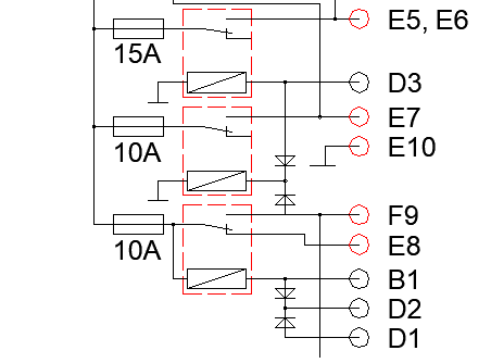
i use three relays and a button behind the fuel filler flap. The button is on D2, B1 is switched by the charge controller and holds the relay. F9 supplies the charge controller, E7 supplies cooling and BMS. D3 is connected to ignition. If no charging takes place for a certain time after pressing the button, the charge controller switches itself off again, just like after the charging process has ended. E8 is the power for forward, and reverse switch and so the car is imobylized during charging, D1 is read by the charge controller (pulled up to 5V) and ends the charging process prematurely. E5 / 6 corresponds to ignition and is not necessary for most
Re: How to detect a Type-2 EVSE connection
Posted: Fri Aug 13, 2021 8:41 am
by EV_Builder
The button could trigger the startup of the charger.
The charger on boot enables a relais which shorts the button.
After a time-out it let's go it's relais or if the signal is correction starts charging...
When the vehicle is switched on you could permanently switch it on and you add a input so the charger knows it's because the vehicle is on.
Something like this is what I was thinking. It's simple and saves 'messing' with the sensitive signals like PP / CP.
The button also has a RGB LED..
Re: How to detect a Type-2 EVSE connection
Posted: Fri Aug 13, 2021 8:53 am
by arber333
EV_Builder wrote: ↑Fri Aug 13, 2021 8:41 am
Something like this is what I was thinking. It's simple and saves 'messing' with the sensitive signals like PP / CP.
I agree CP signal is sensitive. But PP just is! I have a 100% success rate on local EVSE connection with PP signaling. On 43kW Fast EVSE however i had a timing issue. But i solved it by synchronising inserting a plug with pressing a button on EVSE. I havent tested it on Tesla L2 EVSE. I think they need about 20s delay between PP and CP pulldown. I think i will get a chance to test one soon.
Re: How to detect a Type-2 EVSE connection
Posted: Thu May 19, 2022 1:29 pm
by johu
I have integrated above circuit into a Gen2 Tesla charger. So now permanent 12V can be fed in via Pin B12 which is otherwise unused. Its traces are beefy enough to carry the current. CP and GND are stolen from the control board as well. Switched 12V is then send back to what is usually the 12V supply input. So as soon as CP is detected the charger turns on and with it the DC-DC converter, BMS, contactor supply and water pump. In the Volvo conversion 4.5A are consumed and the traces are holding up.
Here's a picture. Red cable not yet soldered to the correct pins, should be on the two bottom ones
Re: How to detect a Type-2 EVSE connection
Posted: Fri May 20, 2022 11:37 am
by catphish
Just for anyone interested, this is my setup for type 2.

- Screenshot at 2022-05-20 12-30-35.png (11.21 KiB) Viewed 2998 times
It applies 2.7k to the CP line, which wakes up the EVSE. It allows 12V on CP to be detected by a microcontroller, and allows the controller to apply 1.5k to CP which instructs the EVSE to close its contactors.
It works well but obviously relies on a MCU. Without a MCU, it probably wouldn't be appropriate, as the CP line is PWM, so I guess you already reached the conclusion that this would be better achieved using PP.
Re: How to detect a Type-2 EVSE connection
Posted: Sun May 22, 2022 2:37 pm
by johu
Alright yes, basically the Tesla charger board pulls down CP and the circuit I added tries to not alter the CP signal at all but just "reads" it