Newb inbound!
I've been planning an EV upgrade for my 1980 rabbit pickup for a long time and planned to use a Gen 3 Prius inverter + Leaf Motor. Due to space constraints i really like the idea of having a combined charger/DCDC/inverter combo (I believe possible with Damien's prius board). Problem is, i went to pick up the e-motor from a local wrecking yard today and they decided to give me the entire Leaf powertrain!
Now, I know the Leafs also have integrated DCDC and charger, but i've been looking around here and on Leaf and other DIY EV forums and can't find out if anyone has been able to hack these functions. Is this correct? If so, I'll likely stick with the prius inverter for now, as I've been designing and 3d printing AmpSeal adapters for it anyway.
thanks!
Gen 2 DC-DC Converter & Charger?
-
johu

- Site Admin
- Posts: 5792
- Joined: Thu Nov 08, 2018 10:52 pm
- Location: Kassel/Germany
- Has thanked: 158 times
- Been thanked: 1028 times
- Contact:
Re: Gen 2 DC-DC Converter & Charger?
Did you get a gen2 Leaf power train? That would be too slick to not use, you know with the inverter mounted directly on the motor.
Apparently, but please someone back me up, the DC/DC converter works as is. The charger needs some hacking. The biggest challenge is to actually fit the "power tower" into your car. Even for my Touran it was too tall.
Oh and thanks for jumping on Patreon
Apparently, but please someone back me up, the DC/DC converter works as is. The charger needs some hacking. The biggest challenge is to actually fit the "power tower" into your car. Even for my Touran it was too tall.
Oh and thanks for jumping on Patreon
Support R/D and forum on Patreon: https://patreon.com/openinverter - Subscribe on odysee: https://odysee.com/@openinverter:9
-
celeron55

- Posts: 776
- Joined: Thu Jul 04, 2019 3:04 pm
- Location: Finland
- Has thanked: 28 times
- Been thanked: 110 times
- Contact:
Re: Gen 2 DC-DC Converter & Charger?
The Leaf inverter is much more beefy than the Toyota one, as with the factory firmware it puts out 500A RMS to the motor. I'd hesitate not to go with the Leaf inverter, given the choice. If the battery as at least 240V nominal voltage, I'd use the factory firmware.
I'm using the gen2 PDM for AC charging, DC-DCing and for CHAdeMO too. The only part I was able to get working by CANbus control was the DC-DC converter, for the rest I've totally lobotomized the brain board in a completely undocumented way. The PDM is externally a very convenient package if you can fit it somewhere, no need to make any charging cables or fuse and contactor boxes yourself, aside from the main battery ones.
The prius gen3 inverter is amazingly compact, but the charging function probably needs more testing and development for one to be able to rely on it in a conversion, you need to set up the charging fuses and contactors yourself, and using only the MG2 output might be a bit weak compared to e.g. the Leaf inverter.
-
Alibro
- Posts: 857
- Joined: Sun Feb 23, 2020 9:24 am
- Location: Northern Ireland
- Has thanked: 271 times
- Been thanked: 150 times
- Contact:
Re: Gen 2 DC-DC Converter & Charger?
You might want to watch this guys videos.
I need a bigger hammer!
-
celeron55
- Posts: 776
- Joined: Thu Jul 04, 2019 3:04 pm
- Location: Finland
- Has thanked: 28 times
- Been thanked: 110 times
- Contact:
Re: Gen 2 DC-DC Converter & Charger?
That guy is doing it the easy way with the Leaf BMS being connected into the system with the original battery pack with the original cell count and voltage. I didn't have that luxury.
He will surely publish his findings and CANbus logs, right?
He will surely publish his findings and CANbus logs, right?
-
Alibro
- Posts: 857
- Joined: Sun Feb 23, 2020 9:24 am
- Location: Northern Ireland
- Has thanked: 271 times
- Been thanked: 150 times
- Contact:
Re: Gen 2 DC-DC Converter & Charger?
I was thinking it the same, that it would be easier with oem bms etc and I'm not in that position either but I'm using a Gen1 motor and inverter so a slightly different situation to you.
He says he will but hasn't yet.
He says he will but hasn't yet.
I need a bigger hammer!
-
zippy500
- Posts: 183
- Joined: Fri Jan 04, 2019 8:42 am
- Location: United Kingdom
- Has thanked: 32 times
- Been thanked: 3 times
Re: Gen 2 DC-DC Converter & Charger?
This would be a nice solution , would save some money too, shame they are so bulking, sure most people with a gen2 have the charger/dcdc sitting on their garage floor 
-
vwbrady
- Posts: 246
- Joined: Mon Dec 16, 2019 1:18 am
- Location: Seattle, WA
- Has thanked: 5 times
- Been thanked: 11 times
Re: Gen 2 DC-DC Converter & Charger?
No Problem!johu wrote: ↑Sat Sep 12, 2020 6:22 am Did you get a gen2 Leaf power train? That would be too slick to not use, you know with the inverter mounted directly on the motor.
Apparently, but please someone back me up, the DC/DC converter works as is. The charger needs some hacking. The biggest challenge is to actually fit the "power tower" into your car. Even for my Touran it was too tall.
Oh and thanks for jumping on Patreon
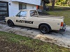
It is a Gen 2 Leaf "Power Tower", yes. It was a quite pleasant surprise TBH. Some US wrecking yards seem to not know how to part EVs. Because of how Nissan integrated everything it kind of looks like an "engine assembly" to them, so that's how they sell it. $350 is a great deal and i'm even thinking of buying spares!
As for packaging i was thinking I could relocate the PDM (Power distro module) portion of the tower to an adjacent spot and 3-d print "cable glands" to connect to the inverter portion.
Here it is in the back of my Model Y.

-
vwbrady
- Posts: 246
- Joined: Mon Dec 16, 2019 1:18 am
- Location: Seattle, WA
- Has thanked: 5 times
- Been thanked: 11 times
-
vwbrady
- Posts: 246
- Joined: Mon Dec 16, 2019 1:18 am
- Location: Seattle, WA
- Has thanked: 5 times
- Been thanked: 11 times
Re: Gen 2 DC-DC Converter & Charger?
Yeah, I wasn't planing on using the Leaf Battery system, but i can know see how communication between BMS and PDM make charging much simpler
-
vwbrady
- Posts: 246
- Joined: Mon Dec 16, 2019 1:18 am
- Location: Seattle, WA
- Has thanked: 5 times
- Been thanked: 11 times
Re: Gen 2 DC-DC Converter & Charger?
I there a way to only use the inverter from the Gen 2 leaf? that may be an option. I would hate to carry around a charger that's nonfunctional. I also do not plan on using CHADeMO, just don't need those charge rates for a toy car.
-
JaniK
- Posts: 391
- Joined: Sun Aug 25, 2019 12:39 pm
- Location: Finland
- Has thanked: 49 times
- Been thanked: 10 times
Re: Gen 2 DC-DC Converter & Charger?
Alltough celeron55 has: "totally lobotomized the brain board in a completely undocumented way."
Do you see a future where an openinverter piggyback mod PCB or other solution would be possible to have the unit working with charger,DC-DC and chademo..?
Do you see a future where an openinverter piggyback mod PCB or other solution would be possible to have the unit working with charger,DC-DC and chademo..?
Any opinions are my own, unless stated otherwise. I take no responsibility if you follow my way of doing things and it doesn't work. Please double check with someone who knows what they are doing.
-
vwbrady
- Posts: 246
- Joined: Mon Dec 16, 2019 1:18 am
- Location: Seattle, WA
- Has thanked: 5 times
- Been thanked: 11 times
Re: Gen 2 DC-DC Converter & Charger?
Let's cross our fingers. I would assume emulating a Nissan BMS would be necessary, but have no clue how complicated that would be.
I'm just beginning to dip my toes into CAN Bus hacking.
-
JaniK
- Posts: 391
- Joined: Sun Aug 25, 2019 12:39 pm
- Location: Finland
- Has thanked: 49 times
- Been thanked: 10 times
Re: Gen 2 DC-DC Converter & Charger?
Yes that sound about right. One would need to tell the unit it is still in a leaf and all is good. Lets hope for that, there is a number of leafs everywhere. I have one too  I could help if i had a plug and play CAN logger? and thats about end of my skillset then.
Any opinions are my own, unless stated otherwise. I take no responsibility if you follow my way of doing things and it doesn't work. Please double check with someone who knows what they are doing.
-
celeron55
- Posts: 776
- Joined: Thu Jul 04, 2019 3:04 pm
- Location: Finland
- Has thanked: 28 times
- Been thanked: 110 times
- Contact:
Re: Gen 2 DC-DC Converter & Charger?
Creating a piggyback mod board should be possible, that's basically what I did as a one-off anyway. I could try to re-trace my steps if somebody sponsored me a PDM.
But it seems to me given enough enough work it can be controlled without modifications using canbus. For that a full setup including the BMS is needed, or alternatively lots of succesful guesswork. Not sure about needing the VCU or inverter.
But it seems to me given enough enough work it can be controlled without modifications using canbus. For that a full setup including the BMS is needed, or alternatively lots of succesful guesswork. Not sure about needing the VCU or inverter.
Re: Gen 2 DC-DC Converter & Charger?
Hello everyone, this topic is also very interesting to me. I am in Moscow, we can buy pdm for $ 50. I am ready to help with the purchase of PDM.
I beg your pardon, I'm writing through a translator.
I beg your pardon, I'm writing through a translator.
Re: Gen 2 DC-DC Converter & Charger?
The power voltage variable control system changes the output from the DC/DC converter built-in PDM (Power
Delivery Module) to 13-15 V to reduce the power consumption according to the status of use of electrical
equipment and that of 12 V battery.
CONTROL DESCRIPTION
The battery current sensor (with battery temperature sensor) measures the battery charge/discharge current
and the battery ambient temperature.
VCM judges the state of use of electric equipment and that of battery according to the measurement, decides
target output voltage of the DC/DC converter, and transmits a target DC/DC converter output signal to PDM
(Power Delivery Module). PDM (Power Delivery Module) changes the output voltage of the DC/DC converter
according to the target DC/DC converter output signal. When an error occurs in the power voltage variable
control system or when a target DC/DC converter output signal is not transmitted to the DC/DC converter due
to error, the DC/DC converter outputs 14 V. VCM detects an error in the DC/DC converter according to a DC/
DC converter status signal transmitted from PDM (Power Delivery Module).
AUTOMATIC 12V BATTERY CHARGE CONTROL
JSCIA0808GB
Revision:
-
johu
- Site Admin
- Posts: 5792
- Joined: Thu Nov 08, 2018 10:52 pm
- Location: Kassel/Germany
- Has thanked: 158 times
- Been thanked: 1028 times
- Contact:
Re: Gen 2 DC-DC Converter & Charger?
Nice work, will you open source it?
Support R/D and forum on Patreon: https://patreon.com/openinverter - Subscribe on odysee: https://odysee.com/@openinverter:9
-
johu
- Site Admin
- Posts: 5792
- Joined: Thu Nov 08, 2018 10:52 pm
- Location: Kassel/Germany
- Has thanked: 158 times
- Been thanked: 1028 times
- Contact:
Re: Gen 2 DC-DC Converter & Charger?
Thats awesome, looking forward to it 
Support R/D and forum on Patreon: https://patreon.com/openinverter - Subscribe on odysee: https://odysee.com/@openinverter:9
Re: Gen 2 DC-DC Converter & Charger?
Hi, I will try to describe in detail how to force the ac-dc converter to work.
The first photo shows a general plan of the rear of the PDM.
For a successful launch, we need to modify the power control board.
https://ibb.co/txx1mzb
The second photo shows the main control board of the PDM, it is located in the upper part.
https://ibb.co/k15ZdB8
We remove the power control board and do the revision from the back. We solder the conductor to the gate of the field-effect transistor, an example in the third photo. If you pull it to the ground then the power corrector starts and the relay is turned on to supply alternating current to the rectifier bridge. CAUTION Do not apply AC power while the relay is on. you can turn on the power corrector only after preliminary charging the capacitors of the power corrector (this happens automatically through a powerful 10 ohm resistor when the AC is turned on)
https://ibb.co/rdVQbBP
Now we start the PWM. The fourth photo shows the revision for starting, in the same way we solder the conductor if it is pulled to the ground, the PWM will start, but there will be no pulse generation on the UCC2895 chip due to the fact that there is no voltage at the input of the error amplifier, it should be higher than 3.6 volts. Look at contact 20.
https://ibb.co/XZWQN90
I ask you not to pay attention to the many wires, I was experimenting)
The fifth photo shows the refinement in order to start the generation of pulses and successfully control the output current.
We need to raise the 6th pin of the MCP4728 microcircuit and solder the conductor to the printed circuit board for the 6th pin and be sure to output GND, since the unit is galvanically isolated from the power key control board.
Now when we supply voltages from 0 to 4 volts, we will change the current of our converter.
https://ibb.co/HxqqM6b
If everything is done correctly, we will see the generation of pulses on pin 18 of the UCC2895 microcircuit as shown in photo # 6
https://ibb.co/RP6GnT0
INCLUDING ORDER
1. Turn on + 12V in a regular way according to the documentation.
2. Directly supply alternating current of 220 volts
3. Turn on the power corrector (tightening on gnd)
4. Turn on the PWM (tightening on gnd)
5. We supply power to the feedback (6 pin of the printed circuit board on the seat of the MCP4728 microcircuit.
https://ibb.co/1vV4QM3
MY THOUGHTS
You can control the MCP4728 using I2C, there is a library in the arduino network) As I understand it, the inverter uses only 1 channel if you apply 4 volts, the inverter will work at full power.
In normal use, the processor gives a command via the I2C interface and the MCP4728 generates a voltage from 0 to 4 volts on channel a. I have not finished the hardware study of the inverter yet, but I'm sure that current and voltage readings are coming to the CPU!
In my project e-baggi will be able to power the consumer with a PDM with a voltage of 220 volts DC from the main battery) and charge too!
Good luck everyone and be careful with high voltage !!!!!!
-
celeron55
- Posts: 776
- Joined: Thu Jul 04, 2019 3:04 pm
- Location: Finland
- Has thanked: 28 times
- Been thanked: 110 times
- Contact:
Re: Gen 2 DC-DC Converter & Charger?
Nice findings.
I documented almost all of the brain board connectors here altough it's in Finnish: viewtopic.php?f=11&t=151&p=1774&hilit=cn100#p1774
You can control the charger and DC-DC converter by just using the isolated I2C bus and the on/off signals going through the ISO7241C chips that are located on the brain board. You don't need a library for the MCP4728 DACs, it's very simple to control using raw I2C. There are a bunch of I2C ADCs on there that give voltage and current readouts. All those are listed in that link.
I think a modboard could suit the PDM quite well. In these two photos are the connections that I used to make it work. This is for DC-DC operation and AC charging. No CHAdeMO. Some traces to the main MCU have been cut, I can't remember which ones, but I'm sure I2C at least.
I have wired an Arduino Nano to all this and it works but the code I'm running is kind of terrible and specific to my conversion.
The wires connected underneath directly to the connector:
- Brown: EVSE PP
- Green: EVSE CP
- Yellow: CANH
- White: CANL
The wires connected to the top side from left to right:
- Green: Constant 5V probably (don't remember)
- Brown: Input 5V to power the rest of the thing on (probably)
- Green: An on/off signal of some sort
- Brown: Another on/off signal of some sort
- (Next to brown): There's a solder blob to short the pins for some reason
- Yellow: I2C
- White: I2C
- Attachments
-
-
-
celeron55
- Posts: 776
- Joined: Thu Jul 04, 2019 3:04 pm
- Location: Finland
- Has thanked: 28 times
- Been thanked: 110 times
- Contact:
Re: Gen 2 DC-DC Converter & Charger?
Then you just...
Easy, right?
I have no idea anymore what goes where, but it's worked for two years now and I'm glad about that because it is a royal pain to remove from the car.
I have no idea anymore what goes where, but it's worked for two years now and I'm glad about that because it is a royal pain to remove from the car.