I can’t give you zombie advice, so feel free to disregard this as irrelevant, but I’ll share what I know works in my T2 using a different controller.
Engine / motor bay - local fuses, relays. Plus Leaf PDM, inverter, motor (obviously!).
VCU - up front. In my case it’s currently housed in the walkway between the front seats. I guess it’s possible I might move it under the dash, but it all works fine as is.
It means I’ve got quite a lot of wiring running back from the VCU to the motor area. Plus control and display stuff going forward to the dash.
I think I decided for problem solving in the final stages it would be a lot easier to have VCU up close to the buttons and pedals, than sat at the back where I couldn’t see any status leds etc.
I would keep the "power" feeds short. So the contactor wires, for the Zombie.
EMI issues woud be first seen on comms or analogue signals. General rules are:
1. Do not run signal or comms wires parallel with high current or voltage cables.
2. If you have issues you can try twisting supply, signal and ground together.
3. Still issues you can switch to shielded twisted wires
Have the zombie in an easy accessible place, for Wifi connectivity or needing to flash it if locked up. You can of course run it on a CAN bus interface for the web settings and flashing which removes this limitation.
So in the short, you can mount the Zombie in the engine bay without an issue.
Thanks a lot for the quick feedback! This helps with a lot of things.
Front part of the car is pretty much all wired now, but the harness connecting the front and rear is giving me slight headaches from trying to plan everything while simulataneously feeling like I still don't understand half of what I'll be needing
Draft of the rear electronics currently:
I still don't love the amount of wires I've to put into the harness nor the amount of relays I've to use but I can't seem to find a way to simplify this.
In the current sketch, the harness going between the rear/front of the car would include (from top to bottom):
- Precharge coil -> Zombie
- Negative contactor coil -> Zombie
- Positive contactor coil -> Zombie
- CAN2: At least IVT shunt <-> Zombie, but I'm hoping to use this with some Arduino's for a couple of other sensors and dash too.
- CAN1: Inverter <-> Zombie
- Inverter power relay -> Zombie
- Cooling relay coil -> Ignition on (I can't seem to figure out a better way of turning on the coolant pump + possible radiator fan)
- Heated rear window coil -> Dashboard switch
- Reverse light relay coil -> Gear selector R (same signal as for Zombie p53 to reverse direction)
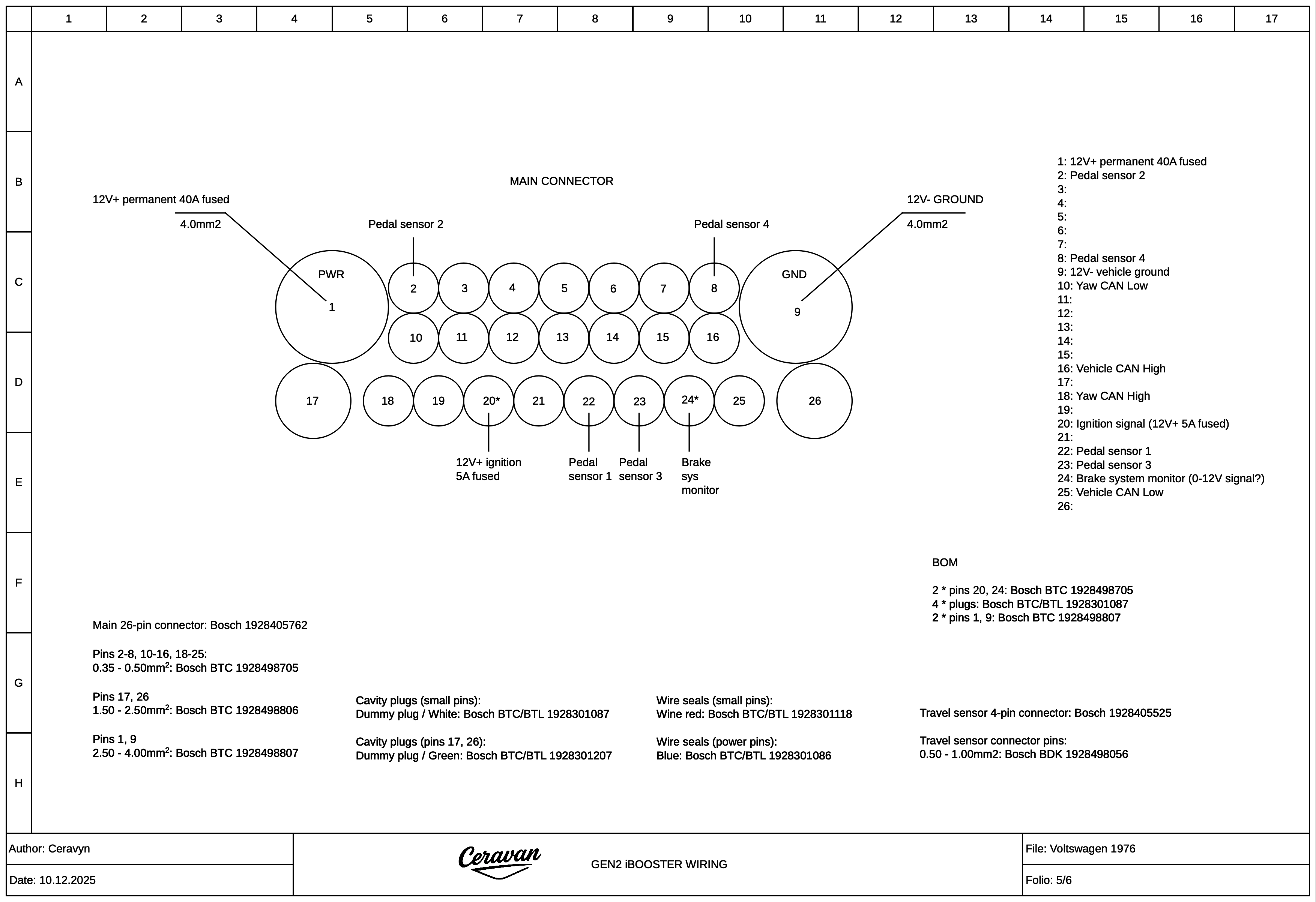
- Brake light relay coil -> iBooster p24 "brake_sys_mon" (shared with Zombie p49 "Brake input")
- Power feed from main fuse -> Front fusebox
- Power feed from main fuse -> Front fusebox
- Turn indicator Left -> Blinker relay
- Turn indicator Right -> Blinker relay
- Tail lights -> Dash light switch
I also still need to figure out stuff like charge ports and possible heaters which would be located in the rear most likely.
... and leave a few extras in the main harness just in case I've overlooked something or want to add more later.
"Dear (public) diary, today I finished the main wiring harness.."
Feels like another milestone again. considering I didn't really have prior knowledge of much of anything and had to bounce ideas back-and-forth with friends and watch countless videos of Youtube to get here.
Like mentioned a lil bit in the previous posts already I wanted to do a full rewire for a few reasons;
- I don't have the original harness anymore, it was in very poor condition and replacements would've been expensive and sometimes of dubious quality... And of course not really built for electric motors in mind.
- I saw potential for upgrades in the original -70's schematics and wanted to make few things a bit more modern way. Mainly headlights are now fed through relay, there's main fuses in the power lines, there's electronic washer fluid pump, standard blade fuses, "camp mode" and so on...
- Opportunity to learn new things! and I kind of want to understand how it all works so I can hopefully also repair whatever malfunction I'll have in the future on the road.
I started working on the HV side plans a lil already too based on what I saw from others in this forum. but the right side of the schematics is still a bit WIP. However the 12V side is 98% wired. There's some minor tweaks still though;
- I had hoped the iBooster would indeed output 0-12V on the pin 24 as suggested earlier in this thread, however currently it seems likely that's not the case for mine and I might need to install a separate brake light switch after all. I'll poke it a lil bit further still though to see if I've miswired or misunderstood something.
- Some components such as radio, coolant fan, etc haven't been installed yet even though wiring is in place.
- Instrument cluster is WIP I might've gotten a lil carried away with it We'll see what comes out of this...
Anyway!
As you probably spotted if you watched the vid above, Zombie has also found its place below the dash and wiring is mostly connected. However I haven't tested powering it on nor poking its firmware at all yet since my laptop deciding to become a desktop a while back and I haven't got a new one yet.
Soon though!
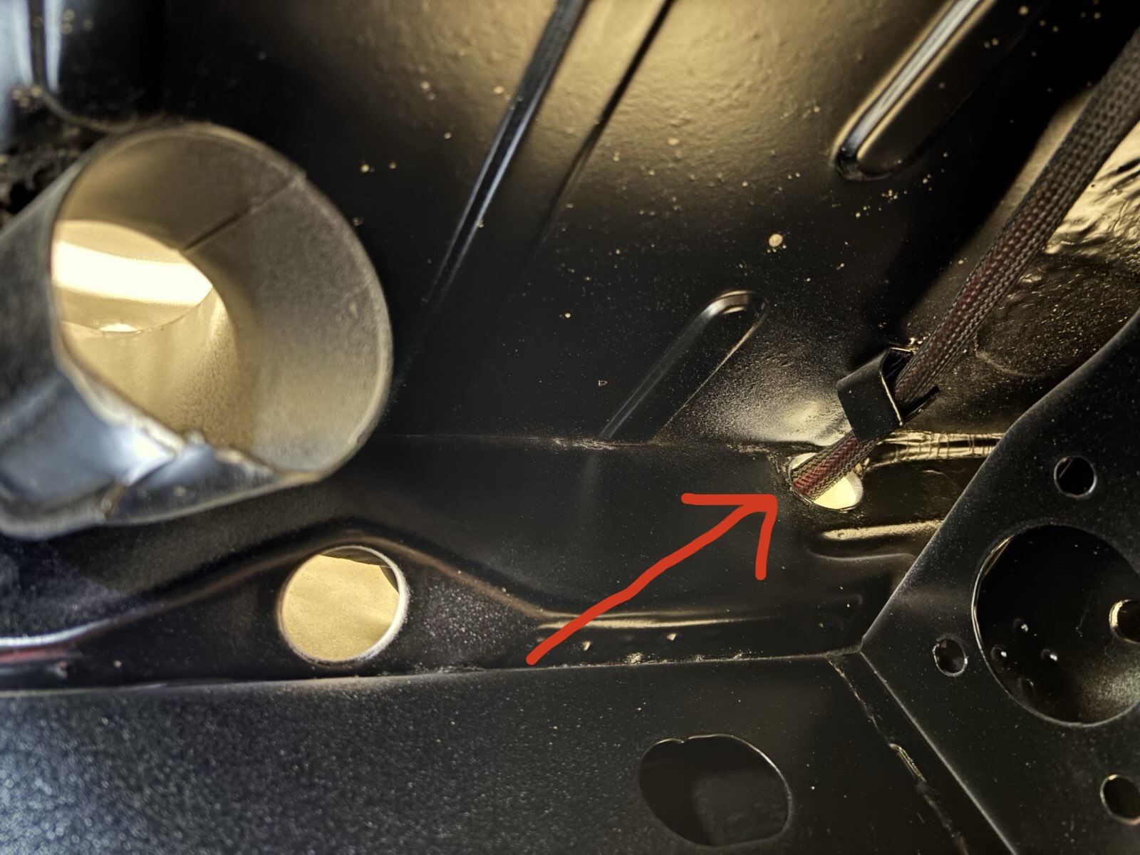
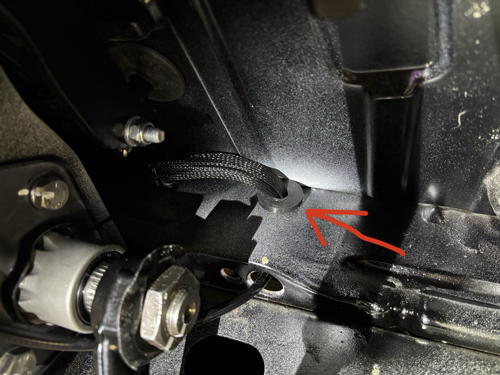
For the main wiring harness I had to design some rubber grommets to avoid the harness from rubbing against the metal edges like so;
Better
All grommets printed out of 85A TPU (Ninjaflex).
So we're somewhat around:
Body rust repairs Suspension Steering Brakes and e-brake Motor mounted 12V system Inverter phases connected to motor Motor cooling system Charging and DC/DC system HV Battery enclosure HVJB and DC-HV wiring
So I still have the TM3 PCS and Leaf PDM, I've been watching Damien's great work on the PCS controller but since I'm learning everything from the scratch I'm still a bit scared it'll go above what my skill levels are.
Leaf PDM sounds a lot easier and the temptation to just bolt that onto the inverter is growing.
Model 3 battery modules and their own BMS pieces seem likewise still just a bit too difficult to implement. Mistakes might've been made with buying those. But that's part of the learning curve.
Kinda feeling slightly stuck now and would need to commit to one path instead of bouncing these back and forth.
Also! All the parts designed for this are now on Cults as I try to migrate into European services:
I'd be interested in your experience in printing the grommets with the 85a tpu. I've done some.in standard tpu but I think its good hard and might rub the cable too much.
Jacobsmess wrote: ↑Wed Feb 25, 2026 10:20 pm
I'd be interested in your experience in printing the grommets with the 85a tpu. I've done some.in standard tpu but I think its good hard and might rub the cable too much.
I've done some water seals to other devices from this same TPU years ago and they're still holding good I think 85A can give quite similar softness as many store bought passthrough grommets or hard-ish rubber seals. Prints with Prusa MK3 and Bambu P1S without problems at least.
I've also tried 80A with mixed results, it's starting to be so soft it's easy to get feed malfunctions with it. But I thought 85A better fit for these anyway.
When printing any soft TPU, I try to keep a loop of filament hanging "freely" at all times so that extruder doesn't need to pull it from the reel. Otherwise sometimes the force it needs to spin the reel in my system might be enough to cause extrusion issues when the filament pulls tight.
Awesome job!
On my build I also added a fuse between DCDC and 12VDC battery to protect the wires.
On the side note, if you ever feel like upgrading the old vw bus wiper motor, there're some threads about it on thesamba. I upgraded it to the vw golf wiper motor and added wiper fluid pump/solenoid - posted details here - https://www.thesamba.com/vw/forum/viewt ... 994%2D1998


 Body rust repairs
 Inverter phases connected to motor
 But that's part of the learning curve.