Error Voltage Measurement [SOLVED]
Error Voltage Measurement
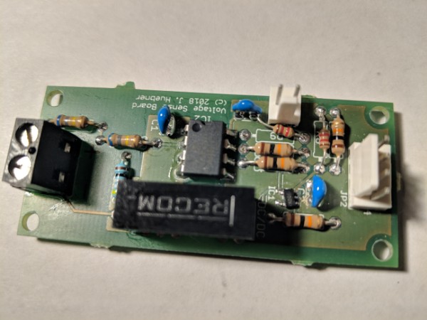
Hello, I have an error measuring the DC bus voltage with the "get udc" command. The command reports a DC bus voltage of 22.71 when my meter shows 0v. Is this normal or perhaps I have not correctly applied the voltage sense fix?
- johu
- Site Admin
- Posts: 5823
- Joined: Thu Nov 08, 2018 10:52 pm
- Location: Kassel/Germany
- Has thanked: 162 times
- Been thanked: 1044 times
- Contact:
Re: Error Voltage Measurement [SOLVED]
Yes it's correct and it only affects the temperature reading. The voltage sense needs to be calibrated with udcofs and udcgain.
With no voltage connected set udcgain=1. Then read udc and set udcofs=udc . Then apply a known voltage and set udcgain=udc/u_known
With no voltage connected set udcgain=1. Then read udc and set udcofs=udc . Then apply a known voltage and set udcgain=udc/u_known
Support R/D and forum on Patreon: https://patreon.com/openinverter - Subscribe on odysee: https://odysee.com/@openinverter:9
-
arber333
- Posts: 3267
- Joined: Mon Dec 24, 2018 1:37 pm
- Location: Slovenia
- Has thanked: 80 times
- Been thanked: 234 times
- Contact:
Re: Error Voltage Measurement
Did you follow calibration instructions? You have to set the voltage offset and gain. So your offset at 0V would be 22V then. If you connect your main bus how much does it show? What is your system voltage? Mine is 380Vdc and if i connect 50Vdc battery i get 60Vdc or more whereas at 360Vdc system is spot on. I like the ATtiny sensing but there are also other options.
EDIT: Sorry i see Johannes has answered already
Re: Error Voltage Measurement
Thanks! The calibration procedure corrected the issue. My voltage is now reported +/- 3v of measured voltage at several intervals between 0 - 350v. I saw no mention of that procedure in the documentation I have been following at https://openinverter.org/invkit.html. Is there another document I should follow once I have my kit assembled?
- johu
- Site Admin
- Posts: 5823
- Joined: Thu Nov 08, 2018 10:52 pm
- Location: Kassel/Germany
- Has thanked: 162 times
- Been thanked: 1044 times
- Contact:
Re: Error Voltage Measurement
I just added it to the wiki which will supersede the traditional pages soon. https://openinverter.org/wiki/index.php ... sor_boards
Support R/D and forum on Patreon: https://patreon.com/openinverter - Subscribe on odysee: https://odysee.com/@openinverter:9
-
arber333
- Posts: 3267
- Joined: Mon Dec 24, 2018 1:37 pm
- Location: Slovenia
- Has thanked: 80 times
- Been thanked: 234 times
- Contact:
Re: Error Voltage Measurement
Hijohu wrote: ↑Thu Mar 28, 2019 7:20 am I just added it to the wiki which will supersede the traditional pages soon. https://openinverter.org/wiki/index.php ... sor_boards
I am looking at your voltage comparator schematic and i am wondering what is the result of 680k resistors. Could i use 360k to 4k7 resistor divider with the same circuit? What would i get out of the battier?
My goal is to get a linear signal that would tell another chip HV voltage in frame from 2.5V to 5V signal. Could that be done with your circuit?
EDIT: could i transfer 400Vdc sensing directly across Si8920 isolation barrier with MCP6001 to get 2.5V to 5V linear?
- johu
- Site Admin
- Posts: 5823
- Joined: Thu Nov 08, 2018 10:52 pm
- Location: Kassel/Germany
- Has thanked: 162 times
- Been thanked: 1044 times
- Contact:
Re: Error Voltage Measurement
Yes with resistors R8 and R7 you can set the offset voltage. I tried with ltspice but I guess you can find the formula somewhere on the web.
The input voltage into the Si8920 chip must be between -250mV to 250mV so goes negative also. The voltage between AOP and AON varies from -1.6 to 1.6V (8.1x gain)
The input voltage into the Si8920 chip must be between -250mV to 250mV so goes negative also. The voltage between AOP and AON varies from -1.6 to 1.6V (8.1x gain)
Support R/D and forum on Patreon: https://patreon.com/openinverter - Subscribe on odysee: https://odysee.com/@openinverter:9
-
arber333
- Posts: 3267
- Joined: Mon Dec 24, 2018 1:37 pm
- Location: Slovenia
- Has thanked: 80 times
- Been thanked: 234 times
- Contact:
Re: Error Voltage Measurement
Hm... i will just use your schematic then since i still have to use another decision making chip to trigger precharge, reset and enable for controler. Also i could use it to input other events like trigger A/C inverter, throttle for a genset or a chargepumpjohu wrote: ↑Thu Apr 18, 2019 7:23 pm Yes with resistors R8 and R7 you can set the offset voltage. I tried with ltspice but I guess you can find the formula somewhere on the web.
The input voltage into the Si8920 chip must be between -250mV to 250mV so goes negative also. The voltage between AOP and AON varies from -1.6 to 1.6V (8.1x gain)
tnx J
Re: Error Voltage Measurement
After reading this discussion I also took a look at the isolated voltage sense schematic of Johannes and noticed a point, not sure if I'm correct though. The pin number 2 of OPA344 is negative supply (V-) and pin 5 is positive (V+) according to the datasheet (http://www.ti.com/lit/ds/sbos107a/sbos107a.pdf). But on the schematic, pin 5 is connected to the ground and pin 2 is connected to VCC. Am I missing something? 
- johu
- Site Admin
- Posts: 5823
- Joined: Thu Nov 08, 2018 10:52 pm
- Location: Kassel/Germany
- Has thanked: 162 times
- Been thanked: 1044 times
- Contact:
Re: Error Voltage Measurement
There is two pinout versions, I selected the weird one (with full intention of course  ) It's the 6001R part.
Support R/D and forum on Patreon: https://patreon.com/openinverter - Subscribe on odysee: https://odysee.com/@openinverter:9
-
arber333
- Posts: 3267
- Joined: Mon Dec 24, 2018 1:37 pm
- Location: Slovenia
- Has thanked: 80 times
- Been thanked: 234 times
- Contact:
Re: Error Voltage Measurement
Hah, it got me scratching my head also. And then I saw the negative R amp on digikey. That figures, programmers like to use negative logic all the time
TNX Johannes


