New Tesla charger board
-
Jack Bauer

- Posts: 4000
- Joined: Wed Dec 12, 2018 5:24 pm
- Location: Ireland
- Has thanked: 153 times
- Been thanked: 1114 times
- Contact:
New Tesla charger board
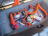
Just a little heads up on a new version of the Gen 2 and Gen 3 charger boards under development. They will feature the ability to switch the pilot signal between standard J1772 protocol and SWCAN. I was donated a Tesla wall connector that finally got installed last week. These can be set to "Tesla only" or legacy mode. A lot of destination chargers in hotels etc are "Tesla only" hence the SWCAN option.
- Attachments
-
I'm going to need a hacksaw
-
tom91

- Posts: 2962
- Joined: Fri Mar 01, 2019 9:15 pm
- Location: Bicester, Oxfordshire
- Has thanked: 328 times
- Been thanked: 847 times
Re: New Tesla charger board
So they use SWCAN instead of the CP? That is interesting but then again quite a pain in the ass interms of being compatible.
These little boxes also want to know the vin of your car and name of your first born?
These little boxes also want to know the vin of your car and name of your first born?
-
Jack Bauer
- Posts: 4000
- Joined: Wed Dec 12, 2018 5:24 pm
- Location: Ireland
- Has thanked: 153 times
- Been thanked: 1114 times
- Contact:
Re: New Tesla charger board
Last of the Gen2 logic boards before the upgrade just in.
New rev will include :
SW CAN for future compatibility with Tesla destination and supercharging and Tesla Chademo adapter. I'm ignoring any legal/moral issues here regards using Tesla charge points. Just making the hardware future proof.
Extra I/O for controlling HVJB.
Onboard Xilinx XC2C64A Coolrunner 2 CPLD for handling extra functions including a BIT (Built In Test) routine and shutdown / wake of the main 5v rail.
ESP32 WiFi header for future upgades. e.g. web interface.
DS1302 battery backed RTC (real time clock) for scheduling charging.
Onboard LEDs to indicate fault states.
Mini USB connector.
Expecting to release in around 6 weeks once tested. Fully backwards compatible with existing software.
- Attachments
-
I'm going to need a hacksaw
-
Kevin Sharpe

- Posts: 1339
- Joined: Fri Dec 14, 2018 9:24 pm
- Location: Ireland and US
- Been thanked: 10 times
Re: New Tesla charger board
Can you bring out any spare I/O to an expansion connector? Might be useful for CCS or other interfaces in the future
Would it be possible to have the option of fitting through hole LED's as an option? Might be useful to have LED's that can poke through the top cover.
This is a personal post and I disclaim all responsibility for any loss or damage which any person may suffer from reliance on the information and material in this post or any opinion, conclusion or recommendation in the information and material.
-
Kevin Sharpe
- Posts: 1339
- Joined: Fri Dec 14, 2018 9:24 pm
- Location: Ireland and US
- Been thanked: 10 times
Re: New Tesla charger board
Looks like we need to get you access to an upgraded Model S/X so you can hack the FC CAN bus and support CHAdeMO and CCS rapid charging 
This is a personal post and I disclaim all responsibility for any loss or damage which any person may suffer from reliance on the information and material in this post or any opinion, conclusion or recommendation in the information and material.
-
Jack Bauer
- Posts: 4000
- Joined: Wed Dec 12, 2018 5:24 pm
- Location: Ireland
- Has thanked: 153 times
- Been thanked: 1114 times
- Contact:
Re: New Tesla charger board
Finally got some time to work on this. Here is a list of the changes from the V3:
Changed from Type B USB to Mini. This will allow the charger lid to close without modification.
Added extra stage of filtering to proximity signal. I have had one customer with a particular brand of EVSE that loves to blow the esd protection diodes in the SAM3 on the proximity line. We modded a V3 board to get around this so rolling this into the V4.
Single wire CAN capability added using the NCV7356. Now uses the exact same switching method between pwm control pilot and sw can as used in the Tesla charger / bms boards. This will allow use of Tesla destination charging, Chademo adapter,CCS adapter and possibly supercharging. All software dependent.
Added two high power DC low side contactor drivers for use with DC fast charge or as general outputs.
Added 3rd CAN channel based around the MCP2517 controller. Allows for high speed as well as FD Can. This extra can channel will allow the Tesla charger to act as a Chademo controller. Just add contactors and a hall current sensor.
Two extra filtered and protected 12v digital inputs. General use or chademo control.
One extra filtered and protected analog input. General use or hall current sensor for chademo control.
Expect to have the pcb mods finished by weekend and prototypes ordered.
- Attachments
-
I'm going to need a hacksaw
-
Jack Bauer
- Posts: 4000
- Joined: Wed Dec 12, 2018 5:24 pm
- Location: Ireland
- Has thanked: 153 times
- Been thanked: 1114 times
- Contact:
Re: New Tesla charger board
Design and pcb layout done. Schematic in PDF format up on Github :
https://github.com/damienmaguire/Tesla- ... ematic.pdf
Design files will be released as soon as I confirm pinouts on a few parts are correct. Particularly the USB socket:)
all comments / suggestions welcome.
https://github.com/damienmaguire/Tesla- ... ematic.pdf
Design files will be released as soon as I confirm pinouts on a few parts are correct. Particularly the USB socket:)
all comments / suggestions welcome.
I'm going to need a hacksaw
-
Jack Bauer
- Posts: 4000
- Joined: Wed Dec 12, 2018 5:24 pm
- Location: Ireland
- Has thanked: 153 times
- Been thanked: 1114 times
- Contact:
Re: New Tesla charger board
Naturally the library part for the USB connector had the pins assigned wrong. That would have been fun. PCBs ordered and design files released.
https://github.com/damienmaguire/Tesla- ... gicBoardV4
https://github.com/damienmaguire/Tesla- ... gicBoardV4
I'm going to need a hacksaw
-
Jack Bauer
- Posts: 4000
- Joined: Wed Dec 12, 2018 5:24 pm
- Location: Ireland
- Has thanked: 153 times
- Been thanked: 1114 times
- Contact:
Re: New Tesla charger board
BOM now uploaded to Github for the V4 design.
The software is currently Tom's version with a few small mods I made for my own needs such as shutdown on reaching a setpoint voltage etc. Once I have some prototypes of the V4 then sw development can start. The V4 is designed for backwards compatability.
The software is currently Tom's version with a few small mods I made for my own needs such as shutdown on reaching a setpoint voltage etc. Once I have some prototypes of the V4 then sw development can start. The V4 is designed for backwards compatability.
I'm going to need a hacksaw
-
Jack Bauer
- Posts: 4000
- Joined: Wed Dec 12, 2018 5:24 pm
- Location: Ireland
- Has thanked: 153 times
- Been thanked: 1114 times
- Contact:
-
Roadstercycle
- Posts: 118
- Joined: Mon Sep 23, 2019 10:28 pm
- Location: California
- Has thanked: 3 times
- Been thanked: 2 times
- Contact:
Re: New Tesla charger board
Hi Jack, Looking to order a new board and wondering the time frame. Going out of town and don't want to miss delivery. Your sales web says 1 to 3 weeks depending on supplier. What are we looking at?
-
Jack Bauer
- Posts: 4000
- Joined: Wed Dec 12, 2018 5:24 pm
- Location: Ireland
- Has thanked: 153 times
- Been thanked: 1114 times
- Contact:
Re: New Tesla charger board
What was the progress on this?Jack Bauer wrote: ↑Thu Apr 04, 2019 3:43 pm Just a little heads up on a new version of the Gen 2 and Gen 3 charger boards under development. They will feature the ability to switch the pilot signal between standard J1772 protocol and SWCAN. I was donated a Tesla wall connector that finally got installed last week. These can be set to "Tesla only" or legacy mode. A lot of destination chargers in hotels etc are "Tesla only" hence the SWCAN option.
Did anyone work out how to switch from J1772 to SWCAN?
Once in SWCAN mode, it looks like the car sends a single byte message every 100mS to control charging:
Code: Select all
can0 30C [1] 00I also have decoded other messages where it sends the TWC serial number, model number, version. And where the car sends the VIN number, SoC etc.
However, what I haven't worked out yet is how to switch to SWCAN. Monitoring a Model 3, it appears comms start using J1772.
When the car is plugged in, the +ve voltage drops to 9V ('Vehicle detected'). After about 600mS the TWC starts generating the 1KHz PWM CP.
About 1.2 seconds later the +ve voltage drops to 6V ('Ready/charging').
Shortly after the comms switch to SWCAN (0 / 5V).
If I simulate the car myself (Diode, 2.74k // 1.3k) the TWC turns on, but stays in J1772 PWM mode.
The SWCAN circuits appears to have an input impedance of 3.5K, which in parallel with the above combination would put the +ve voltage at around 5V (or SWCAN levels). I tried switching this in, but no go.
-
Jack Bauer
- Posts: 4000
- Joined: Wed Dec 12, 2018 5:24 pm
- Location: Ireland
- Has thanked: 153 times
- Been thanked: 1114 times
- Contact:
Re: New Tesla charger board
Progress was I reverse engineered the Tesla board cp input, implemented this on a board. Made the board open source :
https://github.com/damienmaguire/Tesla- ... gicBoardV4
Sold them for a while. Even offered free to anyone willing to do some software and of course no takers. So that board is no longer in production but you are welcome to get some made using the resources on github. Appreciate the share.
https://github.com/damienmaguire/Tesla- ... gicBoardV4
Sold them for a while. Even offered free to anyone willing to do some software and of course no takers. So that board is no longer in production but you are welcome to get some made using the resources on github. Appreciate the share.
I'm going to need a hacksaw
Re: New Tesla charger board
Thanks Damien.
I'll continue to see if I can work out how to enter SWCAN Mode.
Attached is some of the CAN IDs and packets I see between a TWC and a Model 3.
I'll continue to see if I can work out how to enter SWCAN Mode.
Attached is some of the CAN IDs and packets I see between a TWC and a Model 3.
- Attachments
-
 ChargePort.xlsx
- (13.89 KiB) Downloaded 608 times
Re: New Tesla charger board
Quick progress update:
Over the weekend, I wrote some code to decode many of the SWCAN messages:
https://github.com/craigpeacock/Tesla-C ... rt-Decoder
Just need to work out now how to get a TWC to switch to SWCAN mode.
Over the weekend, I wrote some code to decode many of the SWCAN messages:
https://github.com/craigpeacock/Tesla-C ... rt-Decoder
Just need to work out now how to get a TWC to switch to SWCAN mode.
-
Jack Bauer
- Posts: 4000
- Joined: Wed Dec 12, 2018 5:24 pm
- Location: Ireland
- Has thanked: 153 times
- Been thanked: 1114 times
- Contact:
Re: New Tesla charger board
Thanks for the update. I may consider adding it to the new v5 board.
I'm going to need a hacksaw
-
Kevin Sharpe
- Posts: 1339
- Joined: Fri Dec 14, 2018 9:24 pm
- Location: Ireland and US
- Been thanked: 10 times
Re: New Tesla charger board
iirc one of the DIP switches inside the TWC selects between J1772 and SWCAN mode at power up. What are your switch settings?
Edit: here's a reference to the second DIP switch setting. Also note comments re timing;
https://teslamotorsclub.com/tmc/threads ... st-3698196
This is a personal post and I disclaim all responsibility for any loss or damage which any person may suffer from reliance on the information and material in this post or any opinion, conclusion or recommendation in the information and material.
Re: New Tesla charger board
Kevin,
From what I can understand, different firmware on the TWC behave in different ways. I'm running what I believe is the latest (for Gen 2) 4.5.3. In 4.5.3, the DIP switch doesn't appear to do anything. With an oscilloscope on the CP when a Tesla is connected, shows it talks in SWCAN mode regardless of what position the DIP switch is in.
I'll see if I can get a Oscilloscope trace and post it, but as per my post above:
Monitoring a Model 3, it appears comms start using J1772.
When the car is plugged in, the +ve voltage drops to 9V ('Vehicle detected'). After about 600mS the TWC starts generating the 1KHz PWM CP.
About 1.2 seconds later the +ve voltage drops to 6V ('Ready/charging').
Shortly after the comms switch to SWCAN (0 / 5V).
If anyone has a TWC running a firmware version earlier than 4.5.3, I would be interested to hear how the SWCAN comms works in relation to the DIP switch.
-
Kevin Sharpe
- Posts: 1339
- Joined: Fri Dec 14, 2018 9:24 pm
- Location: Ireland and US
- Been thanked: 10 times
Re: New Tesla charger board
That would make sense, I know a lot of commercial sites that deployed TWC were unhappy with the incompatibility with non Tesla cars.
This is a personal post and I disclaim all responsibility for any loss or damage which any person may suffer from reliance on the information and material in this post or any opinion, conclusion or recommendation in the information and material.
Re: New Tesla charger board
Yes, I think the intent is to make it compatible, but practice is a different thing. My father has a Hyundai Kona - It refuses to charge from my TWC running 4.5.3. However, it will charge from older TWC, sometimes you just need to wait 30 seconds before SWCAN times out, and it switches to J1772.Kevin Sharpe wrote: ↑Wed Jun 03, 2020 10:40 am That would make sense, I know a lot of commercial sites that deployed TWC were unhappy with the incompatibility with non Tesla cars.
Re: New Tesla charger board
As promised, this is what a charging session between a Model 3 and TWC 4.5.3 looks like:
- 6sec.png (6.35 KiB) Viewed 14270 times
- Charger idle @ 12V.
- Plug Inserted @ approx 700mS. Signal pulled down to 9V by car's 2.74k resistor ('Vehicle detected').
- Approx 1.3s. TWC starts generating 1KHz CP signal.
- Approx 2.6s comms switch to SWCAN
- Zoomed_out_transition.png (5.16 KiB) Viewed 14270 times
- First 1KHz pulses have positive peaks at 9V ('Vehicle detected')
- Car then switches in 1.3K. Peaks drop to 6V ('Ready/charging')
- 11 pulses later, switches to SWCAN
- Zoomed_in_transition.png (4.56 KiB) Viewed 14270 times
- It appears line is released (not driven by TWC) shortly after 11th pulse.
- SWCAN starts shortly after. Its not yet clear which device starts talking first.
I wonder if this is why some third party vehicles refuse to charge.
More to come....
-
Kevin Sharpe
- Posts: 1339
- Joined: Fri Dec 14, 2018 9:24 pm
- Location: Ireland and US
- Been thanked: 10 times
Re: New Tesla charger board
5% duty cycle indicates digital communications. Here's an extract from IEC61851-1{ed2.0}
It's possible that cars have bugs or that Tesla are doing something strange in the TWC. Certainly early Model S had issues when the EVSE commanded 6A.
This is a personal post and I disclaim all responsibility for any loss or damage which any person may suffer from reliance on the information and material in this post or any opinion, conclusion or recommendation in the information and material.
Re: New Tesla charger board
Thanks.Kevin Sharpe wrote: ↑Sat Jun 06, 2020 6:02 am 5% duty cycle indicates digital communications. Here's an extract from IEC61851-1{ed2.0}
What does IEC61851 define as digital comms? I believe it is ISO 15118-3 HomePlug Green PHY for talking to DC fast chargers.