Hi, I am new on this forum but seeing the recent progress regarding ccs, I couldn't resist trying a few things myself.
I have a tesla and a supercharger nearby and I am very interested to have a look at the ccs communication between them.
Does all the communication go through the cp line using the plc modem?
Which tool can read the traffic? I can see one option is the reprogrammed tplink and the other is the opensource QCA7005 board. Can any of these dump all traffic?
Develop a QCA7000 board?
-
uhi22

- Posts: 1117
- Joined: Mon Mar 14, 2022 3:20 pm
- Location: Ingolstadt/Germany
- Has thanked: 206 times
- Been thanked: 617 times
Re: Develop a QCA7000 board?
Hi and welcome.
Indeed it would be helpful in various situations to just listen to the traffic between the car and the charger. Unfortunately, this goal is not (yet?) reached with the currently open-source knowledge and tooling.
- In pyPLC with the AR7420 homeplug modems there was the plan for a ListenMode, but this is blocked. https://github.com/uhi22/pyPLC#biggest-challenges Most likely a special configuration of the modem is necessary, that nobody knows.
- For the QCA7005 board, the ListenMode was not tried. Since the QCA and the AR7420 are the same manufacturer, I guess they have the same issue, but who knows, maybe it's worth a try.
If somebody has access to a commercial CCS sniffer, it would be really interesting how they solved this...
Github: http://github.com/uhi22 --- Patreon: https://www.patreon.com/uhi22
-
CCSknowitall

- Posts: 106
- Joined: Fri Jun 04, 2021 1:47 pm
- Has thanked: 1 time
- Been thanked: 29 times
Re: Develop a QCA7000 board?
The commercial sniffers I am aware of use ether ST or Vertexcom PLC chips, not Qualcomm.
-
asavage

- Posts: 373
- Joined: Sat May 14, 2022 10:57 pm
- Location: Oak Harbor, Washington, USA
- Has thanked: 359 times
- Been thanked: 118 times
- Contact:
Re: Develop a QCA7000 board?
Is there a relationship between the BMS (whatever BMS is in use) and a foccci/clara package? If so, how are the existing users implementing this relationship?
-
johu

- Site Admin
- Posts: 6768
- Joined: Thu Nov 08, 2018 10:52 pm
- Location: Kassel/Germany
- Has thanked: 383 times
- Been thanked: 1587 times
- Contact:
Re: Develop a QCA7000 board?
Yes, the BMS provides the permissible charge current and SoC. Those values are forwarded to foccci who then sends them to the charger. In my case the BMS data was received from Nissans LBC and then sent on via the CHAdeMO protocol to foccci
Support R/D and forum on Patreon: https://patreon.com/openinverter - Subscribe on odysee: https://odysee.com/@openinverter:9
-
asavage
- Posts: 373
- Joined: Sat May 14, 2022 10:57 pm
- Location: Oak Harbor, Washington, USA
- Has thanked: 359 times
- Been thanked: 118 times
- Contact:
Re: Develop a QCA7000 board?
Does clara have a defined interface to receive BMS communications regarding maximum charge current & voltage, dynamically?
In my use case, it may take some time for the battery heater to sufficiently heat the modules to a temperature when they can begin to accept higher charge current.
In my use case, it may take some time for the battery heater to sufficiently heat the modules to a temperature when they can begin to accept higher charge current.
-
johu
- Site Admin
- Posts: 6768
- Joined: Thu Nov 08, 2018 10:52 pm
- Location: Kassel/Germany
- Has thanked: 383 times
- Been thanked: 1587 times
- Contact:
Re: Develop a QCA7000 board?
It's got the standard OI CAN mapping facility. Examples here https://openinverter.org/wiki/CCS32Clara
Support R/D and forum on Patreon: https://patreon.com/openinverter - Subscribe on odysee: https://odysee.com/@openinverter:9
-
asavage
- Posts: 373
- Joined: Sat May 14, 2022 10:57 pm
- Location: Oak Harbor, Washington, USA
- Has thanked: 359 times
- Been thanked: 118 times
- Contact:
Re: Develop a QCA7000 board?
In the Wiki, udcdivider is listed as having differing (?) functions in two places.
1) Parameters "Division factor from ADC digits to V of external voltage measurement board"
2) Making Clara talk CHAdeMO on the CAN side "some dummy item as the important bit is in the Offset field: the version. In this case I signal non-existent CDM version 10."
Can both co-exist (are they multiplex)?
-
asavage
- Posts: 373
- Joined: Sat May 14, 2022 10:57 pm
- Location: Oak Harbor, Washington, USA
- Has thanked: 359 times
- Been thanked: 118 times
- Contact:
Re: Develop a QCA7000 board?
I'm nailing down some concepts in my mind that I've been black-boxing and ignoring for a couple of years.
Could I: theoretically, read my BMS' CAN and find the data that describes the maximum charge current that is allowed at this moment, and either map it directly to Clara's chargecur (ID 258 in your Wiki example), or use a different MiTM device to filter it/modify it to pass on to Clara?
I'm working with an OEM BMS that spews a lot of CAN, and using a separate CAN MiTM filter seems like a straightforward way of only passing certain MSGIDs to Clara, in addition to being able to pre-condition the data -- though it seems as if the latter could be done directly in the OI interface.
If Clara can ignore the other data that the BMS puts on the CAN bus, and if both foccci and the BMS' CAN can operate at the same bus speed, then it looks as if I would not need a separate MiTM box.
-
f0ld
- Posts: 27
- Joined: Thu Oct 12, 2023 5:41 pm
- Location: Karlsruhe/Germany
- Has thanked: 53 times
- Been thanked: 20 times
Re: Develop a QCA7000 board?
The only User of Focci+Clara that is using it in an actual EV is afaik Johu.
My plan is to use a (modified) version of this project as a retrofit solution to an OEM/legacy EV (Renault Zoe Ph.1) that never had any DC fast charging option. This comes with quit a unique set of problems...
So the BMS to Clara is a question I spend quite some time with in the past weeks...
Originally I intended to use a CAN Bridge that converts my Vehicle Data to the ChaDeMo/OI Can Mapping that is currently used by Johu (not directly to vehicle because Zoe speaks ISO-TP and the bms wants a lot of "holding hands" from the Charge Controller ). But after some time acutally looking into it I found the current implemented solution to not be sufficent to solve my needs for many (special to my usecase) reasons.
I havent decided if I will go the path with the CAN-Bridge (and outsource some of the vehicle integration into it) or even modify the board a lot since I dont like the thought of having 2 boards do the job one could do (but this is quit a deep rabit hole too). On the other hand I am lazy so the first would be easyer
First step will be Bridge+Focci anyways because I (thankfully) have the current version of Focci on my bench test setup and its great for testing.
Either way I will make some kind of my own CAN-SW-Interface (or implement directly my clara "flavor" with Zoe-Can). Maybe that could be available as a config option in clara once I am ready to make a PR.
Lucky me is currently in his university exam phase though and heavily stressed over the next 3 weeks
Maybe I will finally have time then to move from a (similar to Uhis) light bulb demo to actually charging a vehicle
I am exicted to see someone joining in on using clara in the real world!
Will look forward to your results and (for&from now on) I will only be a silent reader in this thread.
Plasma cutter solves all my problems.
-----------------------------------------------------------
Trying to bring a CCS Retrofit to a Renault Zoe.
Github |
-----------------------------------------------------------
Trying to bring a CCS Retrofit to a Renault Zoe.
Github |
-
asavage
- Posts: 373
- Joined: Sat May 14, 2022 10:57 pm
- Location: Oak Harbor, Washington, USA
- Has thanked: 359 times
- Been thanked: 118 times
- Contact:
Re: Develop a QCA7000 board?
I maintain project spreadsheets for my larger projects, and one of them shows that I'm at just over USD$4k in parts* (some of which were dead-end investments) on adding DCFC to an OEM EV that, as your Zoe Ph.1, was not offered with such an option. I've got some of the hardware bits ironed out, but it's been and will continue to be slow going. This is by way of lowering any expectations that you will see a lot of progress from me on this, though it does remain quite high on my ToDo list.
* = does not include tools, an entire quarter of a vehicle I purchased cheaply to drill out all the spot welds and disassemble the inner and outer skins for planning fitment and integration of charge port to the OEM location, and donations to various Patreons related this specific project, such as Johannes, Uwe, and Damien.
* = does not include tools, an entire quarter of a vehicle I purchased cheaply to drill out all the spot welds and disassemble the inner and outer skins for planning fitment and integration of charge port to the OEM location, and donations to various Patreons related this specific project, such as Johannes, Uwe, and Damien.
-
johu
- Site Admin
- Posts: 6768
- Joined: Thu Nov 08, 2018 10:52 pm
- Location: Kassel/Germany
- Has thanked: 383 times
- Been thanked: 1587 times
- Contact:
Re: Develop a QCA7000 board?
In this mapping you could use *any* parameter as its value is ignored (gain=0) and only the offset is sent as is. It's just a way of putting a constant value on the bus
Yes absolutely. Claras CAN speed can be configured. It doesn't mind a lot of CAN because the hardware filters discard all IDs that aren't mapped. By now I could have also done it like this because big endian mapping is now possible (and Nissans LBC sends BE data)
Support R/D and forum on Patreon: https://patreon.com/openinverter - Subscribe on odysee: https://odysee.com/@openinverter:9
-
asavage
- Posts: 373
- Joined: Sat May 14, 2022 10:57 pm
- Location: Oak Harbor, Washington, USA
- Has thanked: 359 times
- Been thanked: 118 times
- Contact:
Re: Develop a QCA7000 board?
Ah, understanding. I found the two Wiki explanations of udcdivider use to be . . . contradictory, but I see that that for your CHAdeMO use case you use it for one thing, whereas in another use case (ie an external analog scaled HV value), udcdivider is used for another.
This wasn't clear to me upon first read, thanks.
This wasn't clear to me upon first read, thanks.
-
uhi22
- Posts: 1117
- Joined: Mon Mar 14, 2022 3:20 pm
- Location: Ingolstadt/Germany
- Has thanked: 206 times
- Been thanked: 617 times
Re: Develop a QCA7000 board?
I have a strange behavior on the Superchargers. The Supercharger provides the 12V on CP if nothing is connected and changes to 9V when foccci is plugged in. Fine until here. Now, normally the charger would start the 5% PWM, but the Supercharger doesn't. Other chargers are starting the PWM quite shortly (below 1s) after plugging-in. To observe the physical state of the CP, I created a small Arduino project, which measures the CP and shows with 2 LEDs very fast, whether the upper and lower voltage of the PWM are fine. https://github.com/uhi22/arduino-controlpilot-observer
With no 5% PWM, the Supercharger also ignores the SLAC requests from foccci, I consider this as normal intended behavior.
I tried different stalls, all behave in the same way. The same stalls are working fine with my Ioniq.
At the moment I could imagine only these root causes:
- Maybe the Supercharger also checks for the PP connection. I do not have connected the PP.
- Maybe the Supercharger has some mechanical detection, which my self-printed CCS inlet does not fulfill. I did not see something, but who knows.
- Maybe the Supercharger is very critical regarding the CP resistance, maybe the foccci is not precise enough. [Edit] Used a 1k/1% resistor and power supply with 12V, and measured the resulting voltage on CP when foccci is connected. This gave 8.9V, so quite near to the intended 9V. Should be fine.
Any ideas?
Github: http://github.com/uhi22 --- Patreon: https://www.patreon.com/uhi22
-
celeron55

- Posts: 804
- Joined: Thu Jul 04, 2019 3:04 pm
- Location: Finland
- Has thanked: 38 times
- Been thanked: 136 times
- Contact:
Re: Develop a QCA7000 board?
Superchargers work perfectly for me with pyPLC. I do have PP connected, I'd start with that. I wonder what johu's circuit was like, because it also worked
-
johu
- Site Admin
- Posts: 6768
- Joined: Thu Nov 08, 2018 10:52 pm
- Location: Kassel/Germany
- Has thanked: 383 times
- Been thanked: 1587 times
- Contact:
Re: Develop a QCA7000 board?
I left PP dangling
Support R/D and forum on Patreon: https://patreon.com/openinverter - Subscribe on odysee: https://odysee.com/@openinverter:9

-
uhi22
- Posts: 1117
- Joined: Mon Mar 14, 2022 3:20 pm
- Location: Ingolstadt/Germany
- Has thanked: 206 times
- Been thanked: 617 times
Re: Develop a QCA7000 board?
Is it possible that the CCS inlet itself already contains some resistor between the PP and PE, so even if leaving the PP wire open, the charger could sense somehow the connected vehicle?
[Edit] Maybe there are even different superchargers. I know, there are V2, V3, V4. All my tests were on V3, and I definitely got a connection with pyPLC some months ago without connecting the PP. Would be strange if they added a more strict detection.
[Edit] Maybe there are even different superchargers. I know, there are V2, V3, V4. All my tests were on V3, and I definitely got a connection with pyPLC some months ago without connecting the PP. Would be strange if they added a more strict detection.
Github: http://github.com/uhi22 --- Patreon: https://www.patreon.com/uhi22
-
muehlpower

- Posts: 698
- Joined: Fri Oct 11, 2019 10:51 am
- Location: Germany Fürstenfeldbruck
- Has thanked: 14 times
- Been thanked: 142 times
Re: Develop a QCA7000 board?
For AC charging, there is a resistance between both plugs between PE and PP, e.g. 220 ohms for 32A current carrying capacity. The PP of the charging station is not connected to the PP of the car. The resistance on the car side is read from the car. How this is done may vary from control unit to control unit. Usually it will be a pull up resistor to 5V. So what does "PP connected" mean?
- Attachments
-
-
uhi22
- Posts: 1117
- Joined: Mon Mar 14, 2022 3:20 pm
- Location: Ingolstadt/Germany
- Has thanked: 206 times
- Been thanked: 617 times
Re: Develop a QCA7000 board?
For CCS, it is even more simple than in the picture (at least from my current understanding): In the plug there is just a 1k5 resistor between PP and PE, like in the right part of the picture above. The car can measure this resistance, e.g. by a pull-up to 5V. Or the car can ignore it, no pull-up, no measurement. The charger does not even see the difference, because it does not measure anything from the PP.
So with "PP connected" I meant that inside of the car there is something like a pull-up or pull-down or a combination of such.
In theory, the charger *could* detect the car by measuring the voltage on the PP, *if* all cars would have a pull-up of a certain value which *would* lead to a certain voltage level. But if the CCS case is the same as the AC case in the picture above, this should not happen.
I think I need to take some measurements.
Github: http://github.com/uhi22 --- Patreon: https://www.patreon.com/uhi22
-
muehlpower
- Posts: 698
- Joined: Fri Oct 11, 2019 10:51 am
- Location: Germany Fürstenfeldbruck
- Has thanked: 14 times
- Been thanked: 142 times
Re: Develop a QCA7000 board?
I took a look at the input circuit of the LIM. PP goes into an R330 and a 47k resistor. The other side of the 47k goes directly into the microcontroller. The second side of the R330 goes into an unknown component with 6 pins. Two of the pins are bridged. The remaining 3 are connected to 5V, GND and a pin of the microcontroller. I suspect that the unknown component is controlled by the microcontroller during the measurement process, connecting the R330 to 5V, and is open the rest of the time to avoid unnecessary power consumption or damage due to static charging. The measurement voltage then reaches the microcontroller via the 47k.
-
uhi22
- Posts: 1117
- Joined: Mon Mar 14, 2022 3:20 pm
- Location: Ingolstadt/Germany
- Has thanked: 206 times
- Been thanked: 617 times
Re: Develop a QCA7000 board?
The 330 ohm pull-up to 5V is confirmed in the picture from the I3 wiki, discussed here: viewtopic.php?p=59932#p59932
It also shows two additional interesting things:
- Directly in the CCS inlet, there is a 4k7 from PP to PE.
- One EVSE side, there is a sense line, PP to the EVSE controller, besides the 1k5 in the connector.
So basically this diagram confirms, that the EVSE controller could do some diagnostics on the PP. But it is not clear, whether the values are officially specified or just an example of BMW.
Measured on the original Ioniq. This has 4.47V on the PP if nothing is connected, and 3.75V if we connect 1k5. This approximately would mean, there is a 330 ohm pull-up to 5V and a 3k pull-down in the car. If the car is sleeping, the static voltage changes to shortly pulsed voltage, something like 1/100 duty cycle and 5Hz. (Only roughly, did only have the multimeter, no osci.)
Cross-linking the PP resistance discussion of the VW charger: viewtopic.php?p=66091#p66091
Conclusion for now: I will wire the focccis PP to the inlet. It has 1k pull up to 3.3V, so the resulting voltage will be only be 2.0V, compared to the 3.75V of the Ioniq. Still the risk that the picky supercharger is not happy with that.
[Edit] Our Indian friends are so kind to publish some more details here: https://morth.nic.in/sites/default/file ... rt_2_F.pdf (This contains a lot of ChaDeMo and CCS stuff.) They say in annex C7: "PP line from vehicle connector to DC supply is mandatory for configurations C and E and optional for configurations D and FF couplers." (Not yet clear, what these configurations mean, something like CCS type 2 and CCS type 1 I guess. [Edit] FF is the CCS2, https://en.wikipedia.org/wiki/IEC_62196#FF)
[Edit2] And in the Indian Figure C.5 we find the 5V, 330 ohm pull-up and 2k7 pulldown in the inlet. This picture is for CCS type 1, not clear whether CCS2 has the same requirements, but could be.
Github: http://github.com/uhi22 --- Patreon: https://www.patreon.com/uhi22
-
asavage
- Posts: 373
- Joined: Sat May 14, 2022 10:57 pm
- Location: Oak Harbor, Washington, USA
- Has thanked: 359 times
- Been thanked: 118 times
- Contact:
Re: Develop a QCA7000 board?
I admit that I am not following this as well as I could, but for confusion's sake . . . a post of mine on another site, from May2023:
https://www.myrav4ev.com/threads/my-own ... post-30114
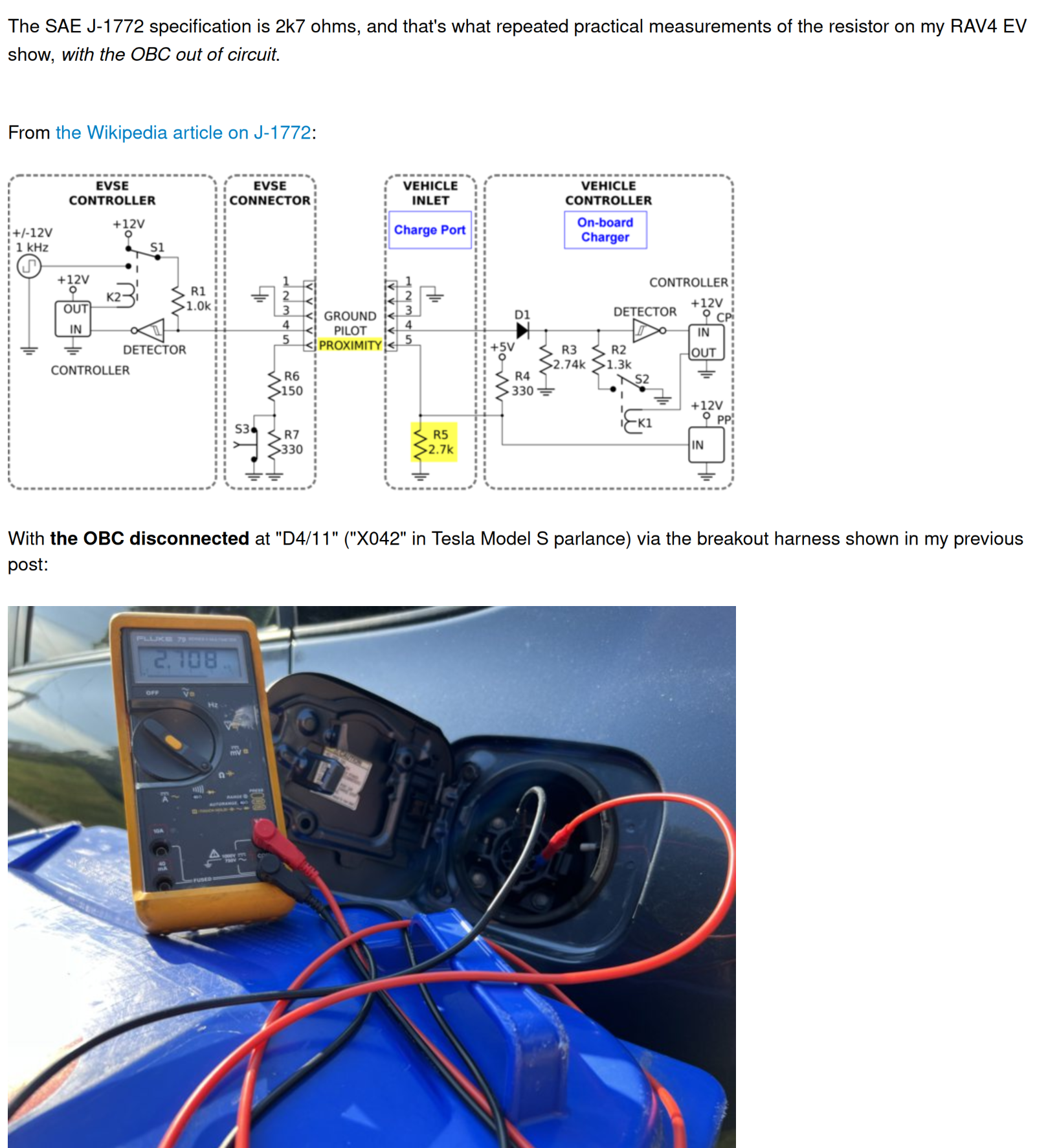
Granted, this is J1772 . . . but the pins are the same ones
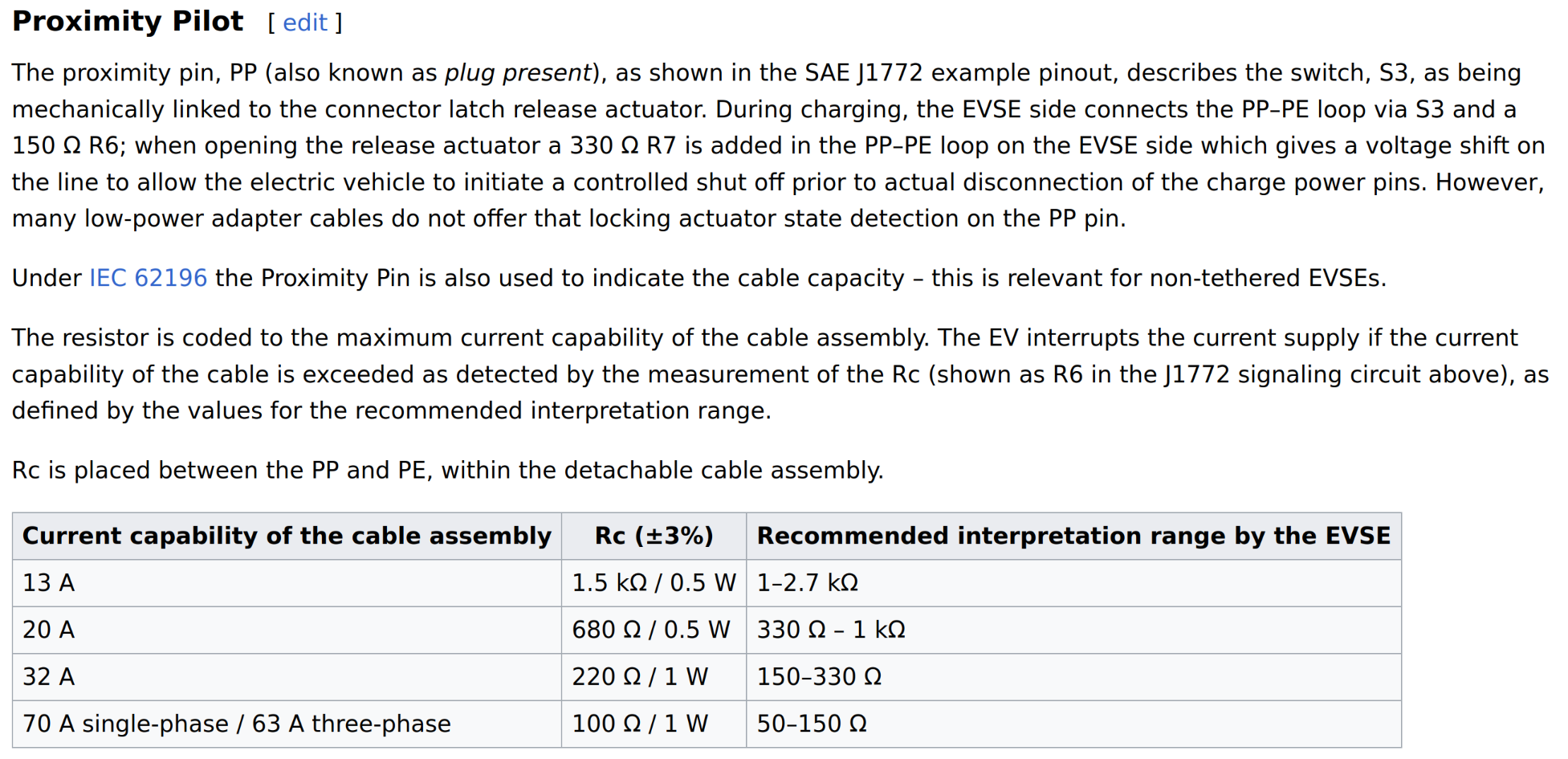
Per the Wiki, the Proximity Pilot is also used (sometimes?) to determine the untethered cable's capacity:
https://www.myrav4ev.com/threads/my-own ... post-30114
Granted, this is J1772 . . . but the pins are the same ones
Per the Wiki, the Proximity Pilot is also used (sometimes?) to determine the untethered cable's capacity:
-
uhi22
- Posts: 1117
- Joined: Mon Mar 14, 2022 3:20 pm
- Location: Ingolstadt/Germany
- Has thanked: 206 times
- Been thanked: 617 times
Re: Develop a QCA7000 board?
Thanks, now all the information leads me to concluding the PP topic:
- The charger (in my case the foccci) shall contain a 330 ohms pull-up to 5V.
- The inlet shall have a 2.7k pull-down.
- This is valid for CCS1 and CCS2. Only the resistors in the plug are different between both variants.
- It seems that a lot of CCS2 chargers do not measure the PP at all, but the specification says that this is mandatory for CCS1 and optional for CCS2.
I'll patch my foccci hardware to fulfill this, and re-test on the supercharger.
Thanks to all for the contributions.
Github: http://github.com/uhi22 --- Patreon: https://www.patreon.com/uhi22
-
uhi22
- Posts: 1117
- Joined: Mon Mar 14, 2022 3:20 pm
- Location: Ingolstadt/Germany
- Has thanked: 206 times
- Been thanked: 617 times
Re: Develop a QCA7000 board?
Success on the Supercharger V3. With the "correct" PP, the PWM starts and we run into the PreCharge loop.
Why not further? Because in the light bulb demo we request 210V, and the charger announced a minimum voltage of 229.99V. Consequently, foccci/clara does not finish the PreCharge, even if the charger itself ignores its own limit and provides the wished 210V in EVSEPresentVoltage.
Did not have the web-interface at hand, so could not change to 230V target immediately.
Logs here: https://github.com/uhi22/clara-logs
Github: http://github.com/uhi22 --- Patreon: https://www.patreon.com/uhi22