Yes, sure let share some more details.
So here is a picture of the MPPT Electronic I designed since I didnt find a suitable Electronic on the market:
Charging the 12V battery is certainly way simpler but also not really effective since it gets full relatively quickly from 200W PV mounted onto the roof.
So my plan was to simply tap into the main battery terminals directly next to the car's ESC.
I am planning to tap into the terminals here:
failry effortless with what's called a "isolation piercing connector" like that one:
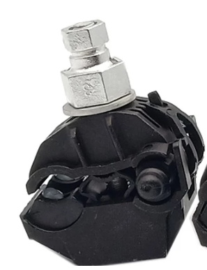
- piercingconnector.PNG (125.12 KiB) Viewed 28744 times
The connector is basically eating carefully through the isolation and is desigend for high voltage, high power outdoor applications. Those connectors are typically designed to tap 230V AC transmission lines from the main line (copper or Aluminium). They can be connected "under power".
From the piercing connector I will use a 1.5mm2 Orange cable (to indicate high voltage) to the MPPT with a ca. 60cm long cable. I aim to put a differential fuse into the line so that it detects fault currents for extra safety. There is also a melting ATO fuse on the PCB just in case.
The PV cable will come down on the driver side, entering under the hood through one of the gaps. I want to use 2x 100W monocrystalline flex panels in series that can be bought for ca. 90€/pc on ebay. That would give ca. 36V MPPT voltage and 45V OC and hence a duty cycle of 10% on the MPPT to generate voltage in the range of 300-400V DC on the output. Since there is no galvanic separation between the main battery GND and the PV GND the isolation must be done with greatest care. I realized the car body is not connected to main battery GND but only to the low voltage battery GND. There will also be a melting fuse on the PV input side of the MPPT.
So my hope was that I dont need CAN bus because the BMS is integrated into the main battery. It will do balancing on its own and I dont aim to set the MPPT to top charge voltage but stop significanlty lower somewhere in the "idle voltage range", maybe around 335V or so.
Then I realized behind the 12V battery there is a way to enter the driver cabin through cable trees already entering the car. So I added an SPI bus connector to the PCB so that a small LCD display can be connected showing the current MPPT Power, current and voltage rating. This SPI is galvanically seperated from all data, VCC and GND lines just in case. It's too risky to bring any potential high voltage cable into the drivers cabin otherwise. Atlernatively one could also use an ESP with Bluetooth to display the data on an android phone but since the MPPT is only powered when the sun is up and in any case is working very intermittendly I decided to use just that display.
The MPPT will power cycle using an analogue hysteresis, e.g. swtiching the MPPT operation if voltage on the low side is greater 28V and goes off if lower than 20V. This way it doesn't go crazy in environments of rapidly changing irradince, e.g. when driving under trees or entering a tunnel