Tesla Charger Support Thread
-
m.art.y
- Posts: 559
- Joined: Sat Jun 06, 2020 6:54 pm
- Location: UK/EU
- Has thanked: 29 times
- Been thanked: 17 times
Re: Tesla Charger Support Thread
Hi, could somebody clarify if US versions of tesla chargers can function as 3 phase after control board replacement and any chance to get full power out of them in Europe? Thanks
-
coleasterling
- Posts: 20
- Joined: Thu Mar 21, 2019 2:27 pm
- Been thanked: 1 time
Re: Tesla Charger Support Thread
You guys have any source for the board connector: SM24B-CPTK-1A-TB(L) ? I can't find one in stock.
-
EV_Builder

- Posts: 1199
- Joined: Tue Apr 28, 2020 3:50 pm
- Location: The Netherlands
- Has thanked: 16 times
- Been thanked: 33 times
- Contact:
Re: Tesla Charger Support Thread
Yes only 3phase + N is needed.
Converting an Porsche Panamera
see http://www.wdrautomatisering.nl for bespoke BMS modules.
see http://www.wdrautomatisering.nl for bespoke BMS modules.
-
qmedia2651

- Posts: 56
- Joined: Tue Oct 06, 2020 4:13 am
- Location: Orlando Florida, USA
Tesla SDU main contactor not closing
My board v5 with commercial firmware have to reset button to start led to Blink wifi working after reset but if power off must reset again.
Any one can have any input on this matter.
Qmedia from Orlando Florida. Working on 1991 300CE Mercedes conversion project.
Any one can have any input on this matter.
Qmedia from Orlando Florida. Working on 1991 300CE Mercedes conversion project.
Re: Tesla Charger Support Thread
Hello,
I have a v3 logic board in my hands. It doesn't output anything to serial monitor. In Arduino IDE I've compiled v3 and v4 code and both upload fine to the board but serial monitor stays blank. Speed is set to 115200. Putty throws error message when trying to connect to the board. Board worked out-of-the-box when installed in the charger but we could never configure its parameters. We've tried two different computers and several usb cables. Any help is appreciated. If you think the board is shot we'll just buy a v5 board.
I have a v3 logic board in my hands. It doesn't output anything to serial monitor. In Arduino IDE I've compiled v3 and v4 code and both upload fine to the board but serial monitor stays blank. Speed is set to 115200. Putty throws error message when trying to connect to the board. Board worked out-of-the-box when installed in the charger but we could never configure its parameters. We've tried two different computers and several usb cables. Any help is appreciated. If you think the board is shot we'll just buy a v5 board.
-
EV_Builder
- Posts: 1199
- Joined: Tue Apr 28, 2020 3:50 pm
- Location: The Netherlands
- Has thanked: 16 times
- Been thanked: 33 times
- Contact:
Re: Tesla Charger Support Thread
Can you elaborate on that sentence?
Converting an Porsche Panamera
see http://www.wdrautomatisering.nl for bespoke BMS modules.
see http://www.wdrautomatisering.nl for bespoke BMS modules.
Re: Tesla Charger Support Thread
Sure thing. It was bought directly from Damien two years ago, I think. It was never configured by anyone (except Damien) but installed directly inside a gen2 charger. Seemed to work as charger was wired directly to a charge port. Now I'd like to check its settings so we could proceed on some proper charging of battery.
-
EV_Builder
- Posts: 1199
- Joined: Tue Apr 28, 2020 3:50 pm
- Location: The Netherlands
- Has thanked: 16 times
- Been thanked: 33 times
- Contact:
Re: Tesla Charger Support Thread
Ok so you opened up the cover and soldered in the USB connector and plugged in the laptop?
Converting an Porsche Panamera
see http://www.wdrautomatisering.nl for bespoke BMS modules.
see http://www.wdrautomatisering.nl for bespoke BMS modules.
-
catphish

- Posts: 955
- Joined: Fri Oct 08, 2021 11:02 pm
- Location: Dorset, UK
- Has thanked: 94 times
- Been thanked: 179 times
Re: Tesla Charger Support Thread
I'm considering buying a Gen 2 charger, but I am worried that there is no way to obtain the SM24B-CPTK-1A-TB(L) connector. Does anyone have any of these spare? Would I be better off hacking in a different connector?
-
EV_Builder
- Posts: 1199
- Joined: Tue Apr 28, 2020 3:50 pm
- Location: The Netherlands
- Has thanked: 16 times
- Been thanked: 33 times
- Contact:
Re: Tesla Charger Support Thread
You can desolder it and reuse it from the Tesla board.
Converting an Porsche Panamera
see http://www.wdrautomatisering.nl for bespoke BMS modules.
see http://www.wdrautomatisering.nl for bespoke BMS modules.
-
catphish
- Posts: 955
- Joined: Fri Oct 08, 2021 11:02 pm
- Location: Dorset, UK
- Has thanked: 94 times
- Been thanked: 179 times
Re: Tesla Charger Support Thread
USB connector was already there. Arduino IDE recognizes the board and I can upload stuff there.EV_Builder wrote: ↑Sat Nov 13, 2021 2:42 pm Ok so you opened up the cover and soldered in the USB connector and plugged in the laptop?
-
Roadstercycle
- Posts: 118
- Joined: Mon Sep 23, 2019 10:28 pm
- Location: California
- Has thanked: 3 times
- Been thanked: 2 times
- Contact:
Re: Tesla Charger Support Thread
I just received my newest Gen 2 board. Couple questions. Is the new firmware in it? The other question is about the 30 pin connector. I ordered the suggested part number but when receiving it the number 1 terminal has been deleted. Damien uses the number one pin so can I just flip it around so the missing pin is on the opposite end? It looks like there's no connections there if it's just a 2 layer board.
- Attachments
-
-
-
EV_Builder
- Posts: 1199
- Joined: Tue Apr 28, 2020 3:50 pm
- Location: The Netherlands
- Has thanked: 16 times
- Been thanked: 33 times
- Contact:
Re: Tesla Charger Support Thread
Yes that's correct. You flip it.
Converting an Porsche Panamera
see http://www.wdrautomatisering.nl for bespoke BMS modules.
see http://www.wdrautomatisering.nl for bespoke BMS modules.
-
catphish
- Posts: 955
- Joined: Fri Oct 08, 2021 11:02 pm
- Location: Dorset, UK
- Has thanked: 94 times
- Been thanked: 179 times
Re: Tesla Charger Support Thread
Yes, see this image from the wiki, pin 30 is not needed:Roadstercycle wrote: ↑Tue Nov 16, 2021 9:00 pm I just received my newest Gen 2 board. Couple questions. Is the new firmware in it? The other question is about the 30 pin connector. I ordered the suggested part number but when receiving it the number 1 terminal has been deleted. Damien uses the number one pin so can I just flip it around so the missing pin is on the opposite end? It looks like there's no connections there if it's just a 2 layer board.
-
m.art.y
- Posts: 559
- Joined: Sat Jun 06, 2020 6:54 pm
- Location: UK/EU
- Has thanked: 29 times
- Been thanked: 17 times
Re: Tesla Charger Support Thread
Hi, I know Tesla and some people here are using 2 gen2 Tesla chargers in parallel for 20 kw charging power. Is it possible to do the same with Tesla gen3 48A US version chargers for use in Europe with 3 phase? Main question is wiring - since gen2 chargers have 3 modules inside wiring 2 chargers for 3 phase in parallel is no problem. I have seen conflicting info whether gen3 48A US version has 2 or 3 modules and I am hesitant to open one if I can't use 2 in parallel since I want a 20 kw AC charging setup. If indeed there is only 2 modules the wiring does not work out for charging on 3 phase or does it? Thanks!
-
janosch

- Posts: 308
- Joined: Tue Jun 30, 2020 9:23 am
- Location: London, UK
- Has thanked: 72 times
- Been thanked: 60 times
- Contact:
Re: Tesla Charger Support Thread
We considered drilling and tapping an extra bleed screw into our Gen2 charger because of our positioning (sideways & upright & high in the cooling circuit).
So we X-Rayed one!
Added picture to the wiki: https://openinverter.org/wiki/GEN2
So we X-Rayed one!
Added picture to the wiki: https://openinverter.org/wiki/GEN2


-
johu

- Site Admin
- Posts: 5810
- Joined: Thu Nov 08, 2018 10:52 pm
- Location: Kassel/Germany
- Has thanked: 162 times
- Been thanked: 1039 times
- Contact:
Re: Tesla Charger Support Thread
Interesting! So current flows top to bottom I guess. Grid filter (2 common mode chokes) PFC stage (two more chokes), TO-247 transistors mounted on the side of the module. Then capacitor bank, transformer, output filter.
Support R/D and forum on Patreon: https://patreon.com/openinverter - Subscribe on odysee: https://odysee.com/@openinverter:9

Re: Tesla Charger Support Thread
Not so easy to see the waterflow.
I found this
- coldplate2.JPG (18.24 KiB) Viewed 4776 times
Thomas A. Edison “I have not failed. I've just found 10,000 ways that won't work"
-
janosch
- Posts: 308
- Joined: Tue Jun 30, 2020 9:23 am
- Location: London, UK
- Has thanked: 72 times
- Been thanked: 60 times
- Contact:
Re: Tesla Charger Support Thread
Wow this is great! Do you have a link to the video? Who is the guy in the picture?
Re: Tesla Charger Support Thread
Not sure i snipped it a while ago. But if I'm not wrong it was "Rich Rebuilds" on YouTube
Thomas A. Edison “I have not failed. I've just found 10,000 ways that won't work"
Re: Tesla Charger Support Thread
Long time lurker, first time poster.
Ordered a Gen 2 V3 and a Gen 3 V2 from Damien last year. Got the Gen 2 working fine and used it for a while. Now getting the Gen3 charger going and have been chasing some issues.
Using the wiring and already installed and proven pack setup in the vehicle, North American, 72A Gen 3 charger, and for testing only, using the chademo charge cables into the charger with a J1772 adapter to a 40A 240V Grizzl-E charger
Got the wiring completed on the charger, and reading 0s for the DC/AC side charger 36000, cable 20000, setV 403V, termination V 400V. AC amps set to 36A
Grizzl-e reads OK, proxy 1.7V, pilot 7.8V. Modules are on, INI1 is H, batt voltage not showing, but I've metered it at 378V. Grounds all common, termination resistor on phase #1 @120 ohms.
Interestingly, I've heard no relays click inside the Gen3 charger at all no matter what we try.
Confirmed all fusing is good, voltage present after all fuses and DC voltage present at each card.
All modules reading 0 v Ac, 0V DC, 0 charge, 0 temp, 00000000000 and more 0.
Much care was taken to ensure that the CAN wires are matched twisted pairs, with Belden foil wire from the charger to the EVBMW board.
Seems like there's something missing? Am I just staring at it too long?
Re: Tesla Charger Support Thread
OK,
I was just staring at it too long.
found a couple things:
the USB and CAN wires on the 20 pin were left unterminated, as we were just testing the system. depinning them one at a time established better communication between the V3 charger and the DM controller. It popped up right away once those were removed.
Damien's video doesnt show him having the CAN/ USB and other wires attached, so that should probably be noted.
problem solved.
-
catphish
- Posts: 955
- Joined: Fri Oct 08, 2021 11:02 pm
- Location: Dorset, UK
- Has thanked: 94 times
- Been thanked: 179 times
Re: Tesla Charger Support Thread
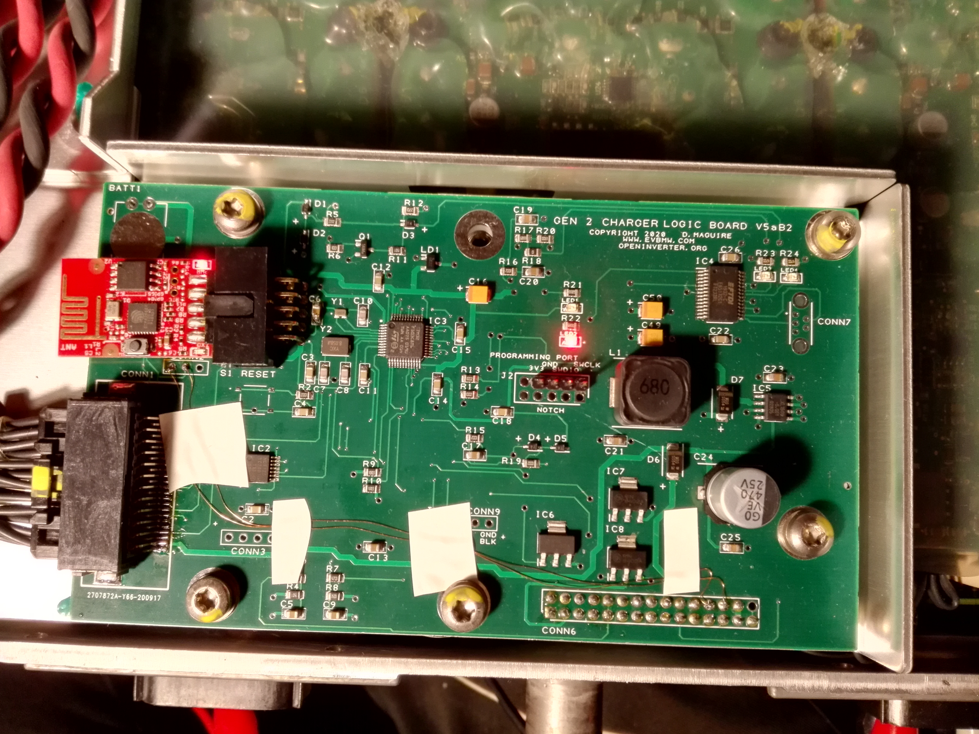
I just wanted to note on this thread that I have successfully tested the Tesla Gen2 Charger 1014963-00-C with Damien's v5 logic board and Johannes's (*ahem* not open source) firmware at low current levels (only 2A without cooling) and everything works correctly. AC and DC voltages are correctly reported, AC and DC current limits are correctly calculated and confirmed with ammeter. Keep up the good work! 
-
catphish
- Posts: 955
- Joined: Fri Oct 08, 2021 11:02 pm
- Location: Dorset, UK
- Has thanked: 94 times
- Been thanked: 179 times
Re: Tesla Charger Support Thread
I just wanted to note that while precharge may not be necessary, there is a 6.6uF capacitor in parallel with the battery connector on each charge module. Connecting all 3 modules in parallel to a 300+ volt battery made enough of a bang that I wouldn't want to switch this without a precharge, and even in testing, i used a precharge resistor before connecting it up. Maybe I'm just a wimpJack Bauer wrote: ↑Fri Mar 22, 2019 7:53 am No need to precharge the charger. It does it itself during startup. Just connect with an appropriate fuse.