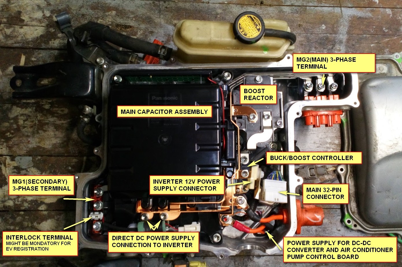
Some changes in pin assignment:
- GIVA - to level shifter 1
- MIVA - another input to level shifter 1
- GIWA - to level shifter 2
- MIVA - another input to level shifter 2
- VH - udc input
- MIVT - tmphs input
- MFIV - desat input
- CPWM - PWM2_N for charging
- MUU - PWM1
- MVU - PWM2
- MWU - PWM3
- GINV and GCNV and GND - ground everything here
- Encoder channel B/Resolver S3
- GND/Resolver center point S1S4
- Encoder channel A or single channel input/Resolver S2
- Resover excitation R1
- Resover excitation R2
- 5V output
- Throttle Input (0-3.3V)
- 2nd Throttle Input (0-3.3V)
- Start input (12V)
- Brake Input (12V)
- Forward (12V)
- Reverse (12V)
- Motor Temperature Input -
- Motor Temperature Input +
- DC contactor output
- Precharge Output
- CANL
- CANH
- GND
- 12V
The only unknown is the "MFIV" fault output from the inverter. Don't know yet what it outputs as "good" and "bad". Right now I'm assuming it outputs 12V for bad and 0V for good.

