A few pictures and meandering thoughts following my recent Tesla gen 2 charger installation with V5 logic board.
-Installation instructions are all on Damien’s GitHub or in the Tesla charger threads. I read both thoroughly before I started and printed off the installation instructions.
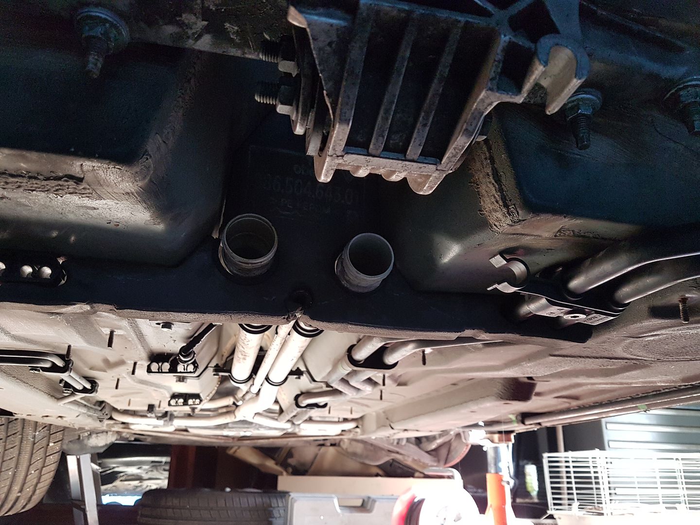
-I used 2mm2 HV wire to run from each charger module and then paralleled them in a separate HVJB nearby. 6mm2 was used to connect directly to the battery via DC HV solar fuses at both charger and HVJB.
- Having a good quality Usart1 lead is necessary. You’ll need some 2.54 pin heads to solder to PCB. It’s helpful to familiarise yourself with ST-Link V2 programming and buy a cheap dongle and fly-leads from eBay for firmware updates.
-Before connecting the AC or DC sides, I configured the charger for testing. Reduced the AC current down to 3amps and set auto enable to off. Once testing is complete, I continued with the installation and configured my preferred settings.
-When incorporating the EVSE wiring, I found out that the charger wants 12vdc a few seconds before applying AC current. I am leaving my charger permanently connected to the 12v for now.
-A good ground on the charger and EVSE earth connection is fundamental. I didn’t at first and Elon was seriously upsetting my Rolec wall pod.
-As I’ve installed this for single phase charging only, I beefed up my L1 and N with 6mm2 cable. The standard 1.5mm2 was getting a little warm

-Note that charge termination happens about 3vdc above termination voltage at which point the EVSE will stop providing AC and return to READY state. For example, I wish my charge to terminate at 392vdc which is about 4.10v per cell. I set my termination voltage at 389VDC to achieve this.
All done!
In conclusion I’m charging at about 10amps across each charge module (I have a 32amp EVSE at home). This is taking about two hours to charge my 16kwh pack. The fact that charging speed is now comparatively so fast, I should be able to comfortably run all my associated systems off the 12v battery during charging (switched on by the 240vac relay coil) without the need to keep the 12v battery topped up.
I still have some work to do in terms of integrating with SIMPBMS.
I'll fit the car's spare wheel cover over the above kit to conceal it.