joromy wrote: ↑Sun Jul 19, 2020 11:51 pm
Very interested, could you show how you made the hardware?
I have done something similar: viewtopic.php?f=10&t=761#p10912
Hey Joromy!
Ahh I wish I had seen your topic I used a 2PNO contactor because I had one lying around.
Your solution is definitely the better one because it's fail safe. Mine has the possibility to short live phases together if the controller malfunctions, which I don't think would be dangerous but would definitely be a nuisance.
I might re-do it with a 3PCO like you have...
I’m very tentatively starting the install on my Gen 2 with V5 logic board. Still waiting for a few parts so not pressing ahead too quickly. However, I powered the unit up on the bench and got the following.
Expected outcome for just applying 12v? I was thinking the menu would appear - but then cant remember whether the boards come preloaded. Grateful for someone’s pearls.
Porsche 986 powered by a Tesla large drive unit. Backwards. Build documented here and Instagram @tesla_porsche here.
Boxster EV wrote: ↑Sat Sep 05, 2020 4:21 pm
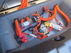
BAD2CD29-D619-4340-9FF4-49BB0AFE451E.jpeg
It looks like your AC-voltage drops to 186V before it shuts off. Might be an undervoltage-switchoff ?
If I see it correctly, you connected the charger through a long (thin) mains cable. Try with something thicker (2,5mm²) for less voltage drop.
Hi,
I was wondering if anyone could tell me if it would be OK to set up the Gen 2 charger like this or if would cause problems. I would like to plug in the J1772 plug first and use the 220 volts to flip a relay to turn on 12 volts to the charger, charge contactor and the water cooling pump. Would this hurt the order of tasks that are supposed to be performed or does really not make a difference? One advantage would be having it plugged in and then when rates are low at night, my 220 volt 50 amp timer would turn on the 220 thus enabling the circuits needed to charge. California really sticks it to you during the day and waiting up until after 10 at night to plug in makes no sense.
Roadstercycle wrote: ↑Mon Sep 07, 2020 12:43 am
Hi,
I was wondering if anyone could tell me if it would be OK to set up the Gen 2 charger like this or if would cause problems. I would like to plug in the J1772 plug first and use the 220 volts to flip a relay to turn on 12 volts to the charger, charge contactor and the water cooling pump. Would this hurt the order of tasks that are supposed to be performed or does really not make a difference? One advantage would be having it plugged in and then when rates are low at night, my 220 volt 50 amp timer would turn on the 220 thus enabling the circuits needed to charge. California really sticks it to you during the day and waiting up until after 10 at night to plug in makes no sense.
Isn’t what you’re asking as simple as just adding 110 or 240VAC relay coil that can switch on the 12vdc for your relevant systems?
Porsche 986 powered by a Tesla large drive unit. Backwards. Build documented here and Instagram @tesla_porsche here.
Why not use the built in 12v out to turn on your charge contactor and water pump?
Leave your timer on the input side of your EVSE. When the timer kicks on, the charger will kick on via J1772, then fire up your contactor and pump. Seems this is a typical use case and the software/hardware is capable in normal use.
The issue is that in reading this forum it is stated that you have to give the Gen 2 charger 12 volt power first before you plug in the EVSE. So by just plugging in the EVSE you do not get 12 volts out unless I missed something. Did I miss something? Do you run 12 volts to the charger all the time or do you switch it on before you plug in the EVSE? So now I'm asking what is the correct series of events? Or does it not matter?
Here's what I'm talking about. From the instructions Page from Damien.
Boot it up!
Give the charger 12V power. The logic board should light up. Connect the battery to DC out, and finally, connect your EVSE to the charger. The modules should light up in the charger, and your battery should begin charging.
Ah yes it is supposed to get 12v hot at all times. It does consume some power though, so if you leave the car for long periods, you may have to accommodate.
Bryson wrote: ↑Tue Sep 08, 2020 5:54 am
Ah yes it is supposed to get 12v hot at all times. It does consume some power though, so if you leave the car for long periods, you may have to accommodate.
So now we are at full loop again. Is it Ok to turn the 12 volt power on at the same time as the 220 volt EVSE is plugged in so you don't get battery drain. There may not be an answer without testing?
The tesla charger is very particular about when it gets ac power. Too soon = fault, too late = fault. Best advice is to try but my sense would be that it will fault on ac too soon.
Thank you Damien.
Since the sequence and timing of events is important a 220 volt turn on contactor for the 12 volt systems to start then an adjustable time delayed 12 volt or 220 volt 4PST contactor for the the 220 volts, control pilot, and Proximity detection to pass through to the charger. That may be the safer way to test.
Roadstercycle wrote: ↑Thu Sep 10, 2020 4:16 am
Thank you Damien.
Since the sequence and timing of events is important a 220 volt turn on contactor for the 12 volt systems to start then an adjustable time delayed 12 volt or 220 volt 4PST contactor for the the 220 volts, control pilot, and Proximity detection to pass through to the charger. That may be the safer way to test.
I’ve been playing with my freshly installed charger today. You’re right, it needs the 12v a few seconds before AC. I’m going to leave mine permanently connected and work towards having the DCDC kick in when the 12v battery dips too low (also for running the water pump during charging).
Porsche 986 powered by a Tesla large drive unit. Backwards. Build documented here and Instagram @tesla_porsche here.
Boxster EV wrote: ↑Sun Sep 13, 2020 8:50 pm
I’ve been playing with my freshly installed charger today. You’re right, it needs the 12v a few seconds before AC. I’m going to leave mine permanently connected and work towards having the DCDC kick in when the 12v battery dips too low (also for running the water pump during charging).
I have a reed switch and magnet in the charge port lid, that turn on a SSR and give 12V to charger and heat/cool controller.
Thomas A. Edison “I have not failed. I've just found 10,000 ways that won't work"
This probably has been touched on before but for reason can't find the answer. If I set my Gen 2 charger voltage at 387 volts what should my turn off voltage be? The same or a little above or below?
Roadstercycle wrote: ↑Wed Sep 16, 2020 1:00 am
This probably has been touched on before but for reason can't find the answer. If I set my Gen 2 charger voltage at 387 volts what should my turn off voltage be? The same or a little above or below?
My V5 cuts AC about 3-4v above termination voltage.
Porsche 986 powered by a Tesla large drive unit. Backwards. Build documented here and Instagram @tesla_porsche here.
On a good note my Gen 2, Rev. L is working with the V5 board that I just received. I could not run it long because of not having the cooling setup yet. Single phase, 220 volt USA. As I increased amp output from 5A to 10A and then 15A the charger increased in output as it should have. WIFI is working too but has the same address as motor inverter, is that normal?
Roadstercycle wrote: ↑Thu Sep 17, 2020 5:11 pm
On a good note my Gen 2, Rev. L is working with the V5 board that I just received. I could not run it long because of not having the cooling setup yet. Single phase, 220 volt USA. As I increased amp output from 5A to 10A and then 15A the charger increased in output as it should have. WIFI is working too but has the same address as motor inverter, is that normal?
Yes the ip address is the same. Your device can only connect to one wifi connection at a time so it does not cause a problem.
Hi, hoping I can get some help with setting up my V5 board. Somehow I must have fat fingered and hit 8 and now to can settings are not matching what I'm seeing others post. Typing 8500 doesn't seem to restore them. Also trying to change the current by typing 75 doesn't work.
Settings Menu
1 - Auto Enable : ON
2 - Modules Enabled : 123
3 - Can Mode : Master
4 - Port Type : 1
5 - Phase Wiring : 1
6 - DC Charge Voltage : 400.000000 0V
7 - AC Current Limit : 13A
8 - CAN0 Speed : 500.000031 0
a - Can Debug : OFF
b - EVSE Debug : ON
t - termination voltage : 0.000000 0V
q - To Quit Menu