Great work! This will certainly help to have handy. Only thing that I have seen asked and answered that was not included is the need to swap encoder pins on some drive units due to a wiring change.invokeperformance wrote: ↑Mon Feb 17, 2020 3:37 pm Damien, I read threw the entire LDU support thread and collected all of the setup and calibration information/FAQ. If you approve I would like to share this information guide I made with your open source information to help new users. If i missed anything please feel free to let me know and i will add it for you!! Cheers keep up the good work!!
Tesla Large Drive Unit Support Thread
-
P.S.Mangelsdorf
- Posts: 772
- Joined: Tue Sep 17, 2019 8:33 pm
- Location: Raleigh, NC, USA
- Has thanked: 96 times
- Been thanked: 94 times
Re: Tesla Large Drive Unit Support Thread
If at first you don't succeed, buy a bigger hammer.
1940 Chevrolet w/ Tesla LDU - "Shocking Chevy" - Completed 2023 Hot Rod Drag Week
1940 Chevrolet w/ Tesla LDU - "Shocking Chevy" - Completed 2023 Hot Rod Drag Week
Re: Tesla Large Drive Unit Support Thread
Thank you so much for putting this together. This will be extremely helpful in getting me going, even though I'm using a SDU.
-
invokeperformance
- Posts: 45
- Joined: Fri Feb 14, 2020 4:23 pm
- Location: Atlanta
- Been thanked: 2 times
- Contact:
Re: Tesla Large Drive Unit Support Thread
Cheers
Re: Tesla Large Drive Unit Support Thread
What wire gauge (AWG or MM) is correct to use for the Molex (23 pin on LDU or 20 pin on SDU) connector that connects to the brain board?
Re: Tesla Large Drive Unit Support Thread
Formerly 92 E30 BMW Cabrio with Tesla power
-
dougyip

- Posts: 76
- Joined: Thu May 09, 2019 2:02 pm
- Location: Vancouver, BC
- Has thanked: 7 times
- Been thanked: 7 times
Re: Tesla Large Drive Unit Support Thread
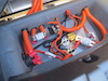
Finally managed to get our spare LDU disassembled and into the oven to test the thermistors. Not quite as easy as we first thought!
We only manged to get our oven up to 146 degC. The values from 170 to 200 degC are from the Steinhart-Hart equation but should be accurate to within 2%. The stock Tesla controller throttles back power when the temp gets above 150 degC. We hope to run up to 200 with the open source controller.
Resistance/Temp
82800 29
46900, 49
22100 75.6
11600 100.4
6610 124.5
4120 146
2440 170
1990 180
1627 190
1337 200
Steinhart-Hart Equation Coefficients: A = 8.72E-04, B=1.43E-04,C=5.60E-07
The two motor thermistors are the same, but are in different locations. We think one is in the end windings and one in the middle, so if one value is used, it should be the max of the two temperatures.
Johannes, are you able to add code into the throttle limit section for motor temp limiting? Is it possible to have the setpoints adjustable and saved as parameters stored on EEProm? Thanks in advance!
-
Roadstercycle
- Posts: 118
- Joined: Mon Sep 23, 2019 10:28 pm
- Location: California
- Has thanked: 3 times
- Been thanked: 2 times
- Contact:
Re: Tesla Large Drive Unit Support Thread
Actually the company has not developed the controller yet. I talked to them and they are still working on it. They are just buying up motors to get ahead of the game.Roadstercycle wrote: ↑Mon Mar 16, 2020 10:01 pm I talked to my Tesla motor provider today about getting you a Tesla model 3 motor for testing. He said that a company in Canada developed a controller for the 3 and ended up buying all his stock and future stock of motors. Bummer.
[/quote]
What company is that?
-
Kevin Sharpe

- Posts: 1345
- Joined: Fri Dec 14, 2018 9:24 pm
- Location: Ireland and US
- Been thanked: 4 times
Re: Tesla Large Drive Unit Support Thread
Please keep this thread focused on LDU support topics...
This is a personal post and I disclaim all responsibility for any loss or damage which any person may suffer from reliance on the information and material in this post or any opinion, conclusion or recommendation in the information and material.
-
invokeperformance
- Posts: 45
- Joined: Fri Feb 14, 2020 4:23 pm
- Location: Atlanta
- Been thanked: 2 times
- Contact:
Re: Tesla Large Drive Unit Support Thread
20 pin connector on logic board to 23 pin amp seal external connector question.
Hey guys I know this may be a stupid question but is there a guide that will tell me exactly where the 20 Ampseal pins on the logic board correspond to to the 23 pins of the ampseal external connector?
I found the "V3 schematic" on GIT hub that outlines the connectors from the logic board and i have the "ampseal pin out V2" .
I just wanted to confirm this is the best way to make the correct connections from the logic board 20 pin connector to my 23 pin external connector. I see the v3 board schematic labels what each amp pin does on the board but I also know there are some unused and linked pins on the 23 out connector and i wanted to ensure the correct wiring.
Finally does the ampseal 1-20 pin count from the logic board start from the top row left to right and bottom row left to right when facing 20 pin outs on the board.
20 pin - "facing pins"
1,2,3,4,5,6,7,8,9,10
11,12,13,14,15,16,17,18,19,20
I already have the 1-23 count layout to the 23 pin ampseal
Thanks
Re: Tesla Large Drive Unit Support Thread
Just saw the comment that there are no hardware interlocks on the SDU and LDU gate drivers(!) This is doin me a small concern, I wonder how much work is involved in adding interlocks. Must investigate now that we have a mandatory four weeks of garage isolation
-
Kevin Sharpe
- Posts: 1345
- Joined: Fri Dec 14, 2018 9:24 pm
- Location: Ireland and US
- Been thanked: 4 times
Re: Tesla Large Drive Unit Support Thread
This is a personal post and I disclaim all responsibility for any loss or damage which any person may suffer from reliance on the information and material in this post or any opinion, conclusion or recommendation in the information and material.
Starting for the first time error codes
Hello, I read through the forum and guides and searched for my problems but could not find the answer.
I'm testing my motor with one Chevy Volt battery that gives 89VDC.
Everything is wired correctly. I started by calibrating the accelerator pedal values. No issues.
Secondly, I changed my UDCMIN to 0 and my UDCSW to 79.
When I flip the ignition switch the precharge relay comes on and I measure 86.6VDC out of the contactor to the motor. The precharge resistor stays on and does not turn off after the ignition is turned on.
I get the following error messages with the ignition on-
302- derate- TMPHSMAX
11- warn- HICUROFS1
1- warn- PWMSTUCK
When I flip my start switch the precharge relay goes off and the main contactor clicks on and off. I get the following messages after the start switch is pushed-
3894 derate CURRENTLIMIT
3895 warn HICUROFS1
3866 derate TMPHSMAX
3894 stop OVERCURRENT.
Is this happening just because I'm testing with lower voltage? I don't want to damage any components and it seems like these codes refer to too much current draw and too high of temperatures.
This board came fully populated and I did not adjust any parameters besides the ones mentioned above.
Thanks!

Re: Tesla Large Drive Unit Support Thread
What is your ocurlim and idcmax limit set to?
Have you tried uploading a known config like this? https://github.com/damienmaguire/Tesla- ... arams.json
Have you tried uploading a known config like this? https://github.com/damienmaguire/Tesla- ... arams.json
Re: Tesla Large Drive Unit Support Thread
idcmax is 5000
ocurlim is -2500
those were the parameters the board came with.
I have not tried anyone's parameter settings.
I see the ocurlim default is 100 but my board came with -2500 as the setting. Should I change it to 100?
ocurlim is -2500
those were the parameters the board came with.
I have not tried anyone's parameter settings.
I see the ocurlim default is 100 but my board came with -2500 as the setting. Should I change it to 100?
Re: Tesla Large Drive Unit Support Thread
Try lower udcmax of like 100 , looks like you are allowing more current than your overall current limit?
Re: Tesla Large Drive Unit Support Thread
I tried to lower udcmax with no results
I changed ocurlim with no results
I started watching spot values and noticed potnom jumps between 0 and 9%. Tmphs jumps between 100c and 23c and tmpm jumps between 0c abs 23c. I plotted them on a graph and they jump up and down like I see them on auto refresh.
Also my din_ocur always reads error. I Data logged din_ocur and got 0
I data logged all the amp and voltage readings through flipping the Start switch and they read 0 the entire time before and after.
In general the web browser sometimes doesn’t load the parameter and spot data and I have to turn ignition off and open a new browser sometimes multiple times to get it to load.
Could there be something wrong with my board?
Re: Tesla Large Drive Unit Support Thread
I think that the overtemp is pulling back the throttle (derate) Looks like you have similar temperature reading issues to those I was having - for me it was caused by one of the mux select pins not being set as an output correctly in software. That fix is posted in the small drive thread, but you'll need to remap it for the large drive unit sensors as I didn't have one to go through... Are you experienced with programming?
I found some WiFi cards don't like connecting well to the inverter. I had a windows PC with a wifi dongle that was a nightmare to connect reliably. I found an older dell laptop running Ubuntu and it's been rock solid. Obviously you need to connect to the SSID and load the page after every power cycle...
I found some WiFi cards don't like connecting well to the inverter. I had a windows PC with a wifi dongle that was a nightmare to connect reliably. I found an older dell laptop running Ubuntu and it's been rock solid. Obviously you need to connect to the SSID and load the page after every power cycle...
Re: Tesla Large Drive Unit Support Thread
That does explain the derate high temp codes but doesn’t give a reason why the main contactor won’t engage and the overcurrent currentlimit Code’s. Unless there’s another software problem related to that one.
I don’t know programming at all. If there’s a new software file, I can upload it to the board. Otherwise I would need specific instructions on how to enter code. This is why I bought a built LDU board and not a blank one.
I don’t know programming at all. If there’s a new software file, I can upload it to the board. Otherwise I would need specific instructions on how to enter code. This is why I bought a built LDU board and not a blank one.
Re: Tesla Large Drive Unit Support Thread
Very true, I would say the overcurrent stop is the reason the main contactor is cutting out immediately - what are your spot current values before start pulse is sent? high current offset you are getting before start when everything should be near zero...
Re: Tesla Large Drive Unit Support Thread
One more clue-
I took the ground signal off my main contactor so when the start is pushed the contactor doesn’t operate. I still get overcurrent and currentlimit codes even with no current going to the inverter. That seems like a sensor/software issue to me.
I took the ground signal off my main contactor so when the start is pushed the contactor doesn’t operate. I still get overcurrent and currentlimit codes even with no current going to the inverter. That seems like a sensor/software issue to me.
Re: Tesla Large Drive Unit Support Thread
I don't know the overcurrent behaviour well, but sounds like the fault condition is already there and is only reacted upon when trying to go into start. Can you share your spot values after precharge? Hopefully somebody with more experience will be able to add more suggestions
Re: Tesla Large Drive Unit Support Thread
Here are my spot numbers and plots.
The spot numbers are ignition on with a successful precharge (DCV is 106)
The plot shows everything measure in amps before during and after the starter switch is pushed and the main contactor goes on and off within a second.
The gauges show 0 before the starter switch is pushed
The second gauges show the values after the starter switch is pushed.
I updated the firmware to the newest version available.
Any help figuring out the issue is appreciated.
Thanks!
- Attachments
-
-
-
-
-
-
-
-
Re: Tesla Large Drive Unit Support Thread
I'm having similar issues to wigman's when bench testing the drive unit with board installed (V4.65). I have things wired up correctly as far as I can tell with 3 contactors, precharge resistor, etc.
I was able to get the main contactor to properly cycle on (with 'start' 12V pulse) exactly once. After that, pulsing the start (pin23) still opens the precharge contactor but wouldn't close the main contactor, which should happen simultaneously AFAIK. Lasterr says TMPHSMAX. Not sure how I could be over temp, I haven't even spun the motor, and I'm working in a cold garage. My test battery voltage is about 84V. I did change UCDSW to 70V and UDCMIN to 0. Really, really hoping I haven't fried the inverter...
Couple of other questions: what does the logic board do with regen after battery reaches 100% SOC when driving down a long hill? Want to make sure the regen goes to zero. I'm sure that's in there somewhere just haven't spotted it yet.
Also, I'm having trouble with throttle calibration trying to use a prius accelerator pedal (0-5V). I've got it wired up to the inverter, am getting response on pot and pot2 but nothing on potnom. What gives? Error message Throttle1. Thanks all, even though I'm in a bit over my head, I'm learning and love that the cutting edge of EV conversions is open source!