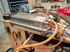
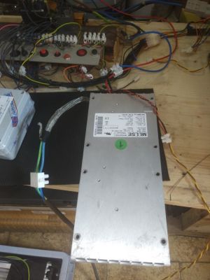
Eltek chargers

Eltek Valere IP67 charger 3kW has extensive documentation where every option is explained in detail.
It is found in Volvo V60 cars under P/N 31394702 or 30659923
https://leafdriveblog.files.wordpress.com/2018/11/eltekguideip67-171710111.pdf
I then red CAN protocol and selected options for my charger.
https://leafdriveblog.files.wordpress.com/2018/11/eltek_canbus_protocol.pdf
For CAN protocol uses standard ID. General ID required to command charger is
ID 02 FF
Data string to command charger is
01 E8 03 6E 0F 3C 00
01 for enable
E8 03 for the max power range 0 to 1000 decimal, 1000=100%, so 0000 to 03E8 in hexa but reversed
6E 0F max voltage same coding as power. I suppose that for 385V send 0A 0F
3C 00 max current same coding as power. For 1 amp send 10 decimal so 00 0A hex in reverse so 0A 00
Rest of calculations:
214V is 5C 08
385V is 0A 0F
390V is 3C 0F
392V is 50 0F
395V is 6E 0F
400V is A0 0F
410V is 04 10
415V is 36 10
420V is 68 10
12A is 78 00
10A is 64 00
8A is 50 00
6A is 3C 00
5A is 32 00
Messages are transmitted at 800ms interval.

Eltek Valere IP20 charger 3kW
P/N HE 241121.030 It is also well documented
https://www.rec-bms.com/datasheet/EltekGuideIP20.pdf
This protocol is for IP20 chargers meant for installation into racks. I confirmed wiring color was ok. I connected DC output to my test battery and AC to my socket.
I connected CAN wires as per document and i got good CAN return report with chargers serial no. https://www.rec-bms.com/datasheet/EVPowerchargerCANprotocol.pdf
After i was sure everything was as it supposed to be i commanded the 02FF telegram that i described in previous Volvo charger
Msg ID 02 FF Data string to command charger is: 01 E8 03 6E 0F 3C 00
-01 for enable, E8 03 for the max power range 0 to 1000 decimal, 1000=100%, so 0000 to 03E8 in hexa but reversed, 6E 0F max voltage 395V same coding as power, hex value x 10, 3C max current same coding as power. For 1 amp send 10 decimal so 00 0A hex in reverse so 0A 00.
- Voltage
- 214V is 5C 08
- 385V is 0A 0F
- 390V is 3C 0F
- 392V is 50 0F
- 395V is 6E 0F
- 400V is A0 0F
- 410V is 04 10
- 415V is 36 10
- 420V is 68 10
- Current
- 12A is 78 00
- 10A is 64 00
- 8A is 50 00
- 6A is 3C 00
- 5A is 32 00
This time 02FF telegram needs repeating at 100ms for the charger to keep alive!
Charger returns with status messages 0305 and 0306 which repeats in 800ms intervals.
- ID 0305
- B0 DCCurrent1
- B1 DCCurrent2
- B2 DCVolt1
- B3 DCVolt2
- B4 power1
- B5 power2
- B6 status
- ID 0306
- B0 DCPower %
- B1 ACPower1
- B2 ACPower2
- B3 ACVoltage1
- B4 ACVoltage2
- B5 Temp secondary
- B6 Temp primary
On how to use the Arduino DUE shield interface with Eltek charger: The way to distinguish from Charging and Non-charging state is the level of PP pin. That is the topmost pin on the front of the shield. Imagine taking a wire from this PP pin, going to the EVSE socket on the side of the car. When you insert the plug you connect GND to PP pin. As i have this PP pin connected to pullup resistor to 3V3 when you are not connected Arduino will read HIGH. But when you are connected this pin will read LOW. This will trigger charging mode and CAN telegram to start charging. I didnt yet program true state machine code but only conditionals using flags. So PP low will trigger PP flag for charging and likewise 12V HIGH input from car ignition will trigger Enable flag signifying Drive mode and all the CAN traffic connected to it.
Now the code.... I am using some of the outsourced drivers for CAN but Collin doesnt mind... https://github.com/collin80/can_common // this are common items for CAN https://github.com/collin80/due_can // this is actual due CAN driver https://github.com/collin80/DueTimer // Time you use to trigger your telegrams https://github.com/collin80/Wire_EEPROM // You need EEPROM to safe your settings in DUE You need to install those into your Arduino libraries folder...
Arduino files and schematic can be found here https://github.com/arber333/Arduino-Due-CAN-shield Basic Eltek code is inside that repository as DCDC_pug_eltek.rar file. Open it and use Arduino with it.
As you run your shield you can connect to it via serial ... USB cable at Use arduino serial tool to issue commands: "h" or "?" to display menu "d" to toggle debug and display actual CAN frames in serial "c" set CAN port - c0 "i" set CAN interval - i500 for 500ms "k" set CAN speed - k500 for 500kbaud
The function for Eltek is declared in the code
       void sendCANframeA() {
       outframe.id = 0x2FF;            // Set our transmission address ID
       outframe.length = 8;            // Data payload 8 bytes
       outframe.extended = 0;          // Extended addresses - 0=11-bit 1=29bit
       outframe.rtr=1;                 //No request
       if(digitalRead(BMS_pin) == HIGH) { // if BMS_pin is high
       outframe.data.bytes[0]=0x00;
       }
       else {
       outframe.data.bytes[0]=0x01; // charger will always stop if BMS doesnt pull the pin down
       }
       outframe.data.bytes[1]=0xE8;  // hex value 1000 for 100%
       outframe.data.bytes[2]=0x03;
       outframe.data.bytes[3]=0x28; // 0F28 dec value 3880 as in 388V
       outframe.data.bytes[4]=0x0F;
       outframe.data.bytes[5]=0x78; // 78=12A -> 0,1A/bit
       outframe.data.bytes[6]=0x00;
       outframe.data.bytes[7]=0x00;
       if(debug) {printFrame(&outframe,1);} //If the debug variable is set, show our transmitted frame
       if(myVars.CANport==0) Can0.sendFrame(outframe);    //Mail it
        else Can1.sendFrame(outframe);
       }