CAN bus with Arduino Due
You can analyse CAN bus traffic using an Arduino Due.
You will need the following:
- An Arduino Due board
- Two SN65HVD230-based CAN transceivers
- An SPI Micro SD storage module (optional)
Here are the steps:
Configure your Arduino IDE
Connecting your computer to the Arduino
Download and install the Arduino IDE on your computer.
Tools -> Board -> Boards Manager. Type "due" in the search box and install "Arduino SAM Boards (32-bits ARM Cortex-M3)".
Connect your computer to the "native" USB port on the Arduino Due board with a USB cable. The Due has two USB ports and they're used for different purposes. The port closer to the DC power connector is the "programming port" and the second is the "Native USB Port".
Make sure your Arduino board is selected with Tools -> Board: "Arduino Due (Native USB port)". Choose also the right port for the DUE from Tools -> Port.
Note: Not all USB cables are capable of transmitting data - some are just charging cables, and it’s almost impossible to tell the difference by external inspection. If your Arduino does not appear as a port, then make sure your USB cable can transmit data by connecting a different device to the cable and verifying that the device shows up on the computer.
Minimal Connectivity Test
File -> Examples -> 01.Basics -> Blink
Sketch -> Upload
Push the reset button on your Due. You should now see a blinking light. Congratulations! You've successfully compiled and loaded your first program and your IDE is working.
Get CAN transceivers working
Hardware Preparations
The Due has two on-board CAN interfaces. However, the board lacks the necessary CAN transceivers to make then useful. You will need to add the transceivers yourself. You can find suitable 3.3V SN65HVD230-based CAN transceivers easily on eBay. They are very cheap. Unfortunately, not all of them work.
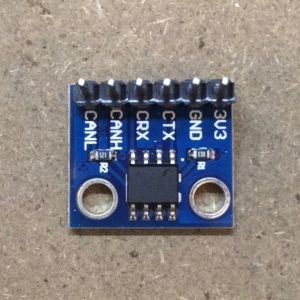
Initially, I tried tiny ones that look like this. They were all faulty.
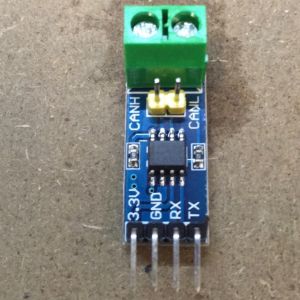
I tried some bigger ones with screw terminals. These all worked perfectly.
Connect your transceivers to the Due board
The CAN0 interface is on the pins marked CANRX and CANTX
The CAN1 interface is on the pins marked DAC0 (RX) and 53 (TX)
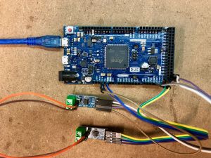
Connect the CAN bus on the two transceivers together (CANL to CANL, CANH to CANH)
Software Preparations
Install Method 1
Tools -> Manage Libraries... Type "due_can" in the search box and install "due_can". If due_can does not appear then try method 2.
Install Method 2
Download https://github.com/collin80/can_common and https://github.com/collin80/due_can as zip files.
Click Sketch > Include Library > Add Zip Library and install the two zip files.
Running the test
Connect your computer to the the "native" USB port on the Arduino Due board with a USB cable and make sure Tools -> Board: "Arduino Due (Native USB port)" is selected.
File -> Examples -> due_can -> CAN_ExtendedPingPong
Sketch -> Upload
Tools -> Serial Monitor
If your CAN transceivers are working properly, you should be rewarded with incrementing numbers in the serial monitor window.
Install GV-RET
Once you've confirmed that your CAN transceivers are working, you can move on to installing the Generalized Electric Vehicle Reverse Engineering Tool (GV-RET). This software will allow your Due CAN transceivers to talk to SavvyCAN.
You need to install a number of libraries (in addition to the due_can library installed in the last section). These are all linked to on the GV-RET website, but a couple of them may not work properly if you install them via that method. I recommend you install the following via the Arduino IDE Library Manager with Tools -> Manage Libraries... :
- SdFat
- DueFlashStorage
Now install the remaining libraries manually. In each case, the installation procedure is:
- Download the .zip file: go to the GitHub webpage, and click on Code -> Download .ZIP
- Rename the file to remove "-master" or any other postfixes. This is important!
- Install the library with Sketch -> Include Library -> Add .ZIP Library... and select the file. Check that the names of the ZIP-files and the main folders in the ZIP-files are exactly as the packages listed below.
You need all of these:
- due_can (installed in previous step)
- can_common (installed in previous section)
- MCP2515
- due_wire
- Wire_EEPROM
Once the libraries are all installed, you can install GV-RET. Again, go to the GitHub webpage, and click on Code -> Download .ZIP.
Expand the .zip file and put the folder in your Arduino sketchbook location. Open the GV-RET project and install it as follows:
File -> Open -> GVRET.ino
Sketch -> Upload
Tools -> Serial Monitor
If it doesn't compile and complains about missing libraries or headers, check the folder names in the Library folder. Remove any "-master" suffixes from the folder names. The folder names should match the library names listed above. If you installed wrong libraries (with a wrong name etc), delete them first by deleting their folders from the arduino folder. For example, for Windows users the folder can be C:\Users\Username\Documents\Arduino\libraries; for Linux/Mac users, the folder can be ~/Arduino/libraries
If everything worked, you should be rewarded with the following messages in the serial console:
Resetting to factory defaults
Using stored values for digital toggling system
Running on CANDue hardware
11977 - ERROR: Could not initialize SDCard! No file logging will be possible!
Build number: 343
Done with init
Congratulations! Your Due is now a powerful CAN sniffer and injection tool. You can connect the CAN-H and CAN-L terminals of a CAN bus transceiver to the CAN bus in your vehicle.
Add logging to SD card (optional)
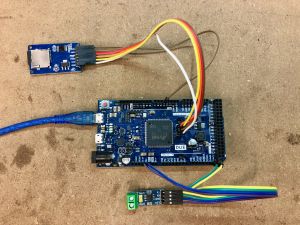
You may have noticed the error message about the SD card. If you have an SPI SD card storage module, your Due will log CAN traffic to this for later analysis. This is ideal if you don't want to have to drive around with a laptop on the passenger seat...
The SD card module needs to be connected to the SPI header (in the middle of the Due board), plus one additional wire to data line 10.
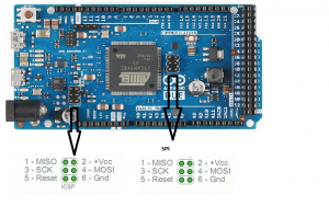
Here are the connections:
| Pin on Due | Pin on SD module |
|---|---|
| SPI MISO | MISO |
| SPI SCK | SCK |
| SPI VCC | VCC |
| SPI MOSI | MOSI |
| SPI GND | GND |
| 10 | CS |
The SD module can be a bit finicky. The GV-RET software defaults to running the SPI bus at 50MHz, but this didn't work for me. So you will need to do a bit of tweaking to fix this.
First of all, check your SD card is working with File -> Examples -> SdFat -> QuickStart. Connect your Due to the Programming USB Port (not the Native USB Port) and upload the program. In the serial console, it will ask for the CS pin. Enter '10'. You should see a little report in the serial console that shows it is working.
It may say you need to reformat your SD card. To do this, go to File -> Examples -> SdFat -> SdFormatter. Edit the source code to set the CS pin to 10 and limit SD clock speed to 4MHz:
const uint8_t chipSelect = 10;
#define SPI_SPEED SD_SCK_MHZ(4)
Upload the program and follow the instructions to format your SD card.
Now go to your GVRET code. Add this line after the line 'SdFat sd;' :
#define SPI_SPEED SD_SCK_MHZ(4)
Find the line 'if (!sd.begin(SysSettings.SDCardSelPin, SPI_FULL_SPEED)) {' and change it to:
if (!sd.begin(SysSettings.SDCardSelPin, SPI_SPEED)) {
Find line SysSettings.SDCardSelPin = CANDUE_SDCARD_SEL; and edit to the pin number you are using.
SysSettings.SDCardSelPin = 10; // pin you are using
Find line settings.autoStartLogging = false; and change
settings.autoStartLogging = true;
That should be enough to get it working. Upload the sketch (this time using the Native USB Port) and you should be rewarded with:
Resetting to factory defaults
Using stored values for digital toggling system
Running on CANDue hardware
Build number: 343
Done with init
At least the error message is gone. So far I haven't managed to get it to log anything to the SD card. It may be the GV-RET configuration needs to be tweaked...
Get started with SavvyCAN
SavvyCAN is a free, open source tool for analysing CAN traffic. Download and install it on your computer. It can be a bit intimidating, so here's a 30 minute tutorial to help you find your feet:
<youtube>kdA5Gdf3FAk</youtube>
If you're too impatient to sit through a tutorial, just dive straight in and connect to your Due. Go back to the Arduino IDE and note down the name of your Due's USB connection. On my Mac, it's "/dev/cu.usbmodem2441". You're now finished with the Arduino IDE, so quit it just in case it interferes with the next step...
In SavvyCAN:
Connection -> Open Connection Window
Add New Device Connection and select the USB connection you noted earlier
Create New Connection
Check "Enable Bus" and set the Speed to match your CAN bus. 500000 is a good guess. You can always change it later.
After a few seconds, you should see "Connected" in the Status field. If it doesn't connect, try pushing the reset button on your Due or click "Reset Selected Device" in SavvyCAN.
Now on to the fun part...
Start hacking
Feel free to add SavvyCAN examples here.
I will add something on my Ampera BMS (once I figure out an easy way to connect to the CAN bus...)