IVT-Shunt Wiring Diagram Error?
Posted: Sat Mar 09, 2024 11:26 pm
Hi all
The Leaf Stack wiring diagram on the Zombieverter wiki page (link below) shows power going to pins a and b of the IVT-shunt's X1 connector. But the datasheet specifies pins a and d for power and ground. Are there multiple/older versions of the IVT-shunt, or is there an error in the wiring diagram?
Also, I do want to thank whoever took the time to put together the leaf wiring diagram. I find it very helpful.
Wiring diagram in question: https://openinverter.org/wiki/File:Zomb ... iring1.png
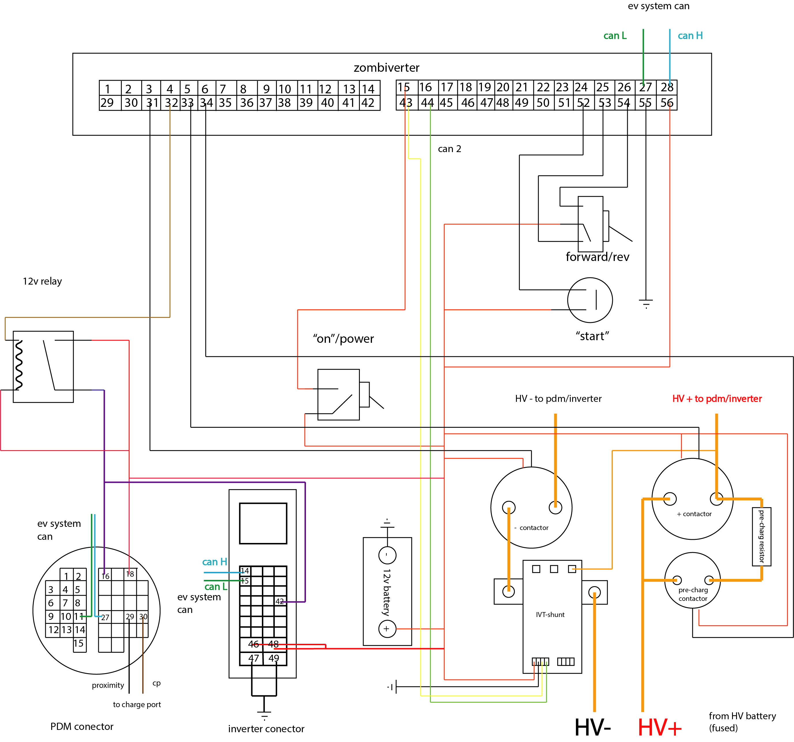
Pin configuration is on page 15 of this datasheet - https://www.isabellenhuette.de/fileadmi ... _V1.02.pdf

The Leaf Stack wiring diagram on the Zombieverter wiki page (link below) shows power going to pins a and b of the IVT-shunt's X1 connector. But the datasheet specifies pins a and d for power and ground. Are there multiple/older versions of the IVT-shunt, or is there an error in the wiring diagram?
Also, I do want to thank whoever took the time to put together the leaf wiring diagram. I find it very helpful.
Wiring diagram in question: https://openinverter.org/wiki/File:Zomb ... iring1.png
Pin configuration is on page 15 of this datasheet - https://www.isabellenhuette.de/fileadmi ... _V1.02.pdf