Page 1 of 1
Testing Newly Soldered v3.0 Board
Posted: Thu Feb 07, 2019 1:07 am
by dima
This is a handy procedure from Johannes
Patreon video
I confirmed that the process works. As you can see from screenshots it is very handy for troubleshooting new "hand-soldered" boards. I am still missing NAND gate and some other components.
Test Firmware:
https://github.com/jsphuebner/stm32-test
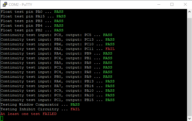
- Screenshot_3.png (9.18 KiB) Viewed 4680 times
Re: Testing Newly Soldered v3.0 Board
Posted: Thu Feb 07, 2019 8:52 am
by johu
Wow, you've actually added it to the web interface! Is that running locally or on esp8266?
EDIT: never mind, the picture gives it away. So could you run it on the esp8266 with your SWD thingy?
Re: Testing Newly Soldered v3.0 Board
Posted: Thu Feb 07, 2019 4:21 pm
by dima
I made some progress with SWD over ESP8266 ...promising but not yet. Just finished soldering v3, took 2 month

Re: Testing Newly Soldered v3.0 Board
Posted: Fri Feb 08, 2019 9:47 am
by Jack Bauer
Wish I could get that web interface to work:)
Re: Testing Newly Soldered v3.0 Board
Posted: Fri Jun 05, 2020 5:40 pm
by davidwagstaff
Is it possible to make this test software a .bin file so it can be uploaded to the STM32 in the same way as the main software for consistency and help us non programmers?
Thanks
Re: Testing Newly Soldered v3.0 Board
Posted: Mon Jul 06, 2020 4:42 pm
by Shaharov
The picture in the post and the picture on github have different resistor values (220R vs 500R) wondering if the value of the resistor is important or if its just to prevent a short to ground? I want to make the testing circuit (judt finished soldering a version 3 as well and want to start testing bit I dont have any 220R or 500R reaistors on hand, but I do have plenty of 10K and 20K available in my parts bin
V3.0 Test software; pre compiled binaries
Posted: Mon Apr 12, 2021 3:13 am
by Bassmobile
davidwagstaff wrote: ↑Fri Jun 05, 2020 5:40 pm
Is it possible to make this test software a .bin file so it can be uploaded to the STM32 in the same way as the main software for consistency and help us non programmers?
Thanks
This seems like a good idea. The toolchain to compile this can be pretty picky to set up on some systems.
If the author of the software isn't going to provide a compiled release and has no objections, I'll post link to HEX / BIN files here.
Archive contains both .hex and .bin compiled binaries
Code: Select all
MD5: a702cd5583ee89a8817a48644b4e42e5 stm32_test.tar.gz
Re: Testing Newly Soldered v3.0 Board
Posted: Sat Oct 16, 2021 1:22 pm
by kay183
Hi!
What is a
Window Comparator and
Inhibit Circuitry?
Re: Testing Newly Soldered v3.0 Board
Posted: Sat Oct 16, 2021 6:23 pm
by johu
The 2901 comparator that checks the AC currents are within a given window (min/max) and the NAND tree that checks for that window comparator, the desat and the mprot signal to be all high.
Re: Testing Newly Soldered v3.0 Board
Posted: Wed Oct 20, 2021 4:45 pm
by kay183
Thanks for the tip. I checked the test board, everything is fine. The resistors correspond to the nominal values, all the necessary pins are connected.
The inputs of the comparator 2901, have the following readings:
5 - 0.26v
4, 6 - 0.82v
7 - 0.26v
8 - 0.26v
9, 11 - 2.46v
10 - 0.26v
accordingly, the output is 0.0v
Also on the 3 input NAND (PA3) - 0.0v
Processors are bought in China, maybe they are fake? Or do I misunderstand something?
Re: Testing Newly Soldered v3.0 Board
Posted: Wed Oct 20, 2021 7:30 pm
by johu
5, 7, 8 and 10 must be above 0.82V and below 2.46V. Check your input resistor network.
Re: Testing Newly Soldered v3.0 Board
Posted: Thu Oct 21, 2021 8:52 am
by kay183
If you apply 5V as indicated on the test board, then the pins P5, P3, P4, P8 of the test board will be 5V*(10k /(47k+10k))=0.88V. But when we installed the inverter, then we get the following diagram:
The chart shows that at the input of the inverter, there is one more voltage divider and the lower shoulder of the divider will not be 10K, and (10K*(3.3 to+4,7 K)/(10K+(3.3 K+4.7 K)=4.4 K and, respectively, the voltage at point 1 (at the output of the test board) will be the same 5V*(4.4/(47k+4.4 k))=0.43 V and then consider the voltage divider on the inverter board. 0,43*(4.7/(3.3+4.7))=0.25V
This is the voltage from the dividers if the PA5 of the microcontroller is installed as an input.
If I swap R1 and R2, then PA5 should get 1.18 V.
Rlower shoulder=(47к*(3.3к+4,7к)/(47к+(3.3к+4.7к)=6.8к
U1=5V*(6.8/(10k+6.8к))=2.02в
Upa5=2,02*(4.7к/(3.3+4.7к))=1,18В
Do you think I'm thinking right or am I wrong somewhere?
Re: Testing Newly Soldered v3.0 Board
Posted: Thu Oct 21, 2021 11:23 am
by johu
Ah, so Dimas diagram is perhaps from the time when there was no on-board divider. Yes you are right, the values must be changed. In fact R2 should be no longer necessary.
Re: Testing Newly Soldered v3.0 Board
Posted: Fri Oct 22, 2021 12:47 pm
by kay183
Ok, i swaped resistors in the divider and now i have 1.2V at PA5, PB0 at the comparator inputs. Output of the comparator is 3.7V. But on the 3rd pin (PA3) NAND I have 0V. PA3 on the microcontroller in the test mode working as input or as output? If it's works as input, maybe i need connect SIG_MPROT at the external connector to 5V? It have internal divider on the invertor board.
I added a 510OHM resistor for SIG_MPROT, as on other pins, and now all the tests are passed.
As a result, the following scheme of the test board turned out.
Is that correct?