Page 20 of 29
Re: Develop a QCA7000 board?
Posted: Sat Feb 17, 2024 1:38 pm
by uhi22
johu wrote: ↑Sat Feb 17, 2024 9:29 am
I can't get the toolchain to compile it myself to work.
At which step are you stuck? I'd like to improve the user manual to be more helpful.
Re: Develop a QCA7000 board?
Posted: Sat Feb 17, 2024 1:41 pm
by uhi22
Ooops, this was a classical "floating quote button error". On the mobile, marked muehlpowers sentence, searched the quote button (it was below), now we have a wrong quote

Re: Develop a QCA7000 board?
Posted: Sat Feb 17, 2024 6:00 pm
by uhi22
johu wrote: ↑Sat Feb 17, 2024 9:29 am
What is the most github-ish way to built a binary of every commit or something?
https://www.jenkins.io/solutions/github/
If thought to the end, Jenkins could not only make a build and put the results somewhere, it could also run unit-tests, tests on target, code checker, and publish the results in a way, where the car automatically fetches it and flashes it to the control unit. (Just dreaming, but it is possible
)
Re: Develop a QCA7000 board?
Posted: Sun Feb 18, 2024 1:56 pm
by davefiddes
johu wrote: ↑Sat Feb 17, 2024 9:29 am
What is the most github-ish way to built a binary of every commit or something?
Github Actions are free for Open Source projects. I have a branch that does 90% of what you want here:
https://github.com/davefiddes/stm32-sin ... -build.yml
It would need a final step to publish the binaries. I'll put together a PR for your consideration.
Re: Develop a QCA7000 board?
Posted: Sun Feb 18, 2024 3:38 pm
by uhi22
Finally (hopefully really finally

) the light bulb demo works on the supercharger. The root cause why it did not work sounds strange, but I have no better explanation. It was hanging in the cableCheck loop. Why? Because the SuperCharger seems to monitor the voltage on the PP. After correcting the pull-up-circuit to 330 ohm and 5V, and 3k pull-down, it nevertheless did NOT work. I scoped the PP line, and found that there are strange "ripples" of ~100mV on this. Where do they come from? Because also on the 5V supply there are the same. Why? Finally I found, that the LED driver transistors were the wrong types. Instead of the NPN with integrated resistors, they were normal NPN. So the controller pushed a lot of current to the basis, and this lead to voltage drops of the 5V, in the rhythm of the blue LED blinking during cable check. After replacing the transistors, the 5V and the PP volage are stable, and the supercharger is happy.
So the conclusion is: Just make it right, then it will work
Logs from the todays successful runs on five different types of chargers here:
https://github.com/uhi22/clara-logs
BTW: All five chargers were happy with the new "locally administrated" MAC address.
[Edit] Also number 6, a quite old Efacec triple, accepted the MAC.
Re: Develop a QCA7000 board?
Posted: Sun Feb 18, 2024 3:48 pm
by johu
Oh!
Great you worked it out.
Are the same wrong transistors on the board you sent me?
Re: Develop a QCA7000 board?
Posted: Sun Feb 18, 2024 4:35 pm
by uhi22
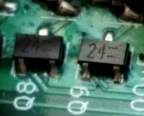
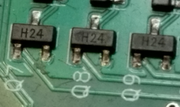
Hm, not sure. Two ways to find this out: Measure the supply current, while you turn off and on an LED. If this leads to significant current jumps (>20mA), you are affected. Or: Measure with a multimeter in diode-check-mode, whether the B-E voltage is 0.7V (bad) or much higher (good). The good ones should be marked with
"2E" or something like this. either "24=" for the hand-populated boards, or "H24" for the jlc populated boards. Both are fine.
- image.png (87.34 KiB) Viewed 9286 times
- image.png (87.47 KiB) Viewed 9286 times
Re: Develop a QCA7000 board?
Posted: Sun Feb 18, 2024 7:00 pm
by catphish
I love your (I assume 3D printed) light bulb test rig
Re: Develop a QCA7000 board?
Posted: Sun Feb 18, 2024 7:12 pm
by uhi22
Yes, it's basically my first self-designed and self-printed project. Lot of room for optimizations, but at least it works
[Edit] Something is happening with this thead. It shows 2315207 views, and the number is increasing fast. Google scanning? Or ChatGPT?
Re: Develop a QCA7000 board?
Posted: Tue Feb 20, 2024 10:43 pm
by johu
Just got reminded of the separate wakeup thread so moved related posts there:
viewtopic.php?p=65022#p65022
Re: Develop a QCA7000 board?
Posted: Wed Feb 21, 2024 6:16 pm
by johu
Added Daves github magic to Clara also. You can now always find latest binaries here:
https://github.com/uhi22/ccs32clara/actions (click on the topmost run)
Re: Develop a QCA7000 board?
Posted: Wed Feb 21, 2024 6:39 pm
by uhi22
Wow, great, and soo easy when knowing how. Thanks.
Any idea how to bring a software version number into the software, so that in case of troubles, we can see in the console log and in the web interface, which version was used? At the moment is just kind of "parameter compatibility version", but does not change per build. Maybe calling "git describe --tags" into the make process, and use its output in a const string.
Re: Develop a QCA7000 board?
Posted: Thu Feb 22, 2024 9:06 am
by uhi22
Got a parcel today. But: "330" is not 330ohms, beginners fault.
Re: Develop a QCA7000 board?
Posted: Thu Feb 22, 2024 5:49 pm
by davefiddes
I've raised a
PR to embed the git version information into the firmware. The existing VER macro is used to generate the "version" spot value. When the database is downloaded over CAN this will update. The version generated uses git describe which means that release versions will take on the most recent git tag (e.g. v0.22.B). Development versions show how many commits after the last tag and the commit short hash (e.g. v0.22.B-68-gb821a5). This will allow releases and development builds from the Github Actions to be distinguished. Local developer builds with uncomitted changes show up with a "-dirty" suffix (e.g. v0.22.B-68-gb821a5-dirty). Hope this helps.
Re: Develop a QCA7000 board?
Posted: Thu Feb 22, 2024 6:18 pm
by celeron55
Rate my CCS charge session
Didn't have the HV side connected, but I thought I set up everything else. This "log" format doesn't exactly produce the reason why it goes from ServiceDiscovery to WaitForChargerShutdown though. I'll probably have to figure out a means of bringing the UART outside of the enclosure in a waterproof way (there's an NC pin in the external connector in V4, right?), but here's hoping someone spots something in this, or confirms it looks normal.
Re: Develop a QCA7000 board?
Posted: Thu Feb 22, 2024 7:23 pm
by johu
The StopReason is "CANTimeout" because you're not feeding the CanWatchdog with zeros. Set DemoControl=Standalone to overcome
Re: Develop a QCA7000 board?
Posted: Thu Feb 22, 2024 7:58 pm
by uhi22
celeron55 wrote: ↑Thu Feb 22, 2024 6:18 pm
Rate my CCS charge session
How did you produce this log? Looks quite nice.
Re: Develop a QCA7000 board?
Posted: Thu Feb 22, 2024 8:28 pm
by celeron55
uhi22 wrote: ↑Thu Feb 22, 2024 7:58 pm
How did you produce this log? Looks quite nice.
By commanding openinverter-can-tool with this shell line:
Code: Select all
d=$(date +%Y-%m-%d_%H%M%S); while true; do date "+%Y-%m-%d_%H%M%S" >> local/foobar_${d}.dumpall; oic -n22 dumpall >> local/foobar_${d}.dumpall; sleep 5; done
Or, to spread it out on multiple lines to actually make it readable:
Code: Select all
d=$(date +%Y-%m-%d_%H%M%S)
while true; do
    date "+%Y-%m-%d_%H%M%S" >> local/foobar_${d}.dumpall
    oic -n22 dumpall >> local/foobar_${d}.dumpall
    sleep 0.5
done
Re: Develop a QCA7000 board?
Posted: Thu Feb 22, 2024 8:31 pm
by celeron55
johu wrote: ↑Thu Feb 22, 2024 7:23 pm
The StopReason is "CANTimeout" because you're not feeding the CanWatchdog with zeros. Set DemoControl=Standalone to overcome
Sounds like I probably should feed it with zeroes instead of setting that mode? So, I should map something on CAN to write a zero into CanWatchdog. What's the maximum interval this should happen at?
Re: Develop a QCA7000 board?
Posted: Thu Feb 22, 2024 9:02 pm
by johu
https://openinverter.org/wiki/CCS32Clar ... e_CAN_side
"Map to 0x102 message at some arbitrary bits with gain=0 so it sets canwatchdog=0 whenever it is received. This makes sure charging stops if the CAN bus is disturbed."
Of course it can be any other message. Since you're using gain=0 the contents does not matter
Timeout is 1s
Re: Develop a QCA7000 board?
Posted: Fri Feb 23, 2024 5:39 am
by celeron55
From a systems integration and safety standpoint it's probably best to set the CAN watchdog to look for the BMS message that updates ChargeCurrent. You definitely want charging to stop if you stop getting that value from the BMS.
The only problem is, my BMS sends that value only every 500ms to keep bus traffic at a reasonable level. Maybe it's enough, but I can't afford to lose any messages. Maybe I'll just make the watchdog slower. Or maybe I'll move that value to a faster message from the BMS if there are empty bytes in some of them.
Re: Develop a QCA7000 board?
Posted: Fri Feb 23, 2024 5:54 am
by uhi22
I'd propose to change the timeout to 5 seconds in Clara, so that even with a one-second BMS message there is sufficient tolerance.
Re: Develop a QCA7000 board?
Posted: Fri Feb 23, 2024 6:04 am
by celeron55
I usually use a timeout of 2 to 5 seconds in my CAN based systems. It doesn't make sense to aim for lower as you only lose flexibility and transmission error tolerance with no benefit.
For my case, I already modified my CAN messages. They were kind of stupid anyway.
I think it would be nice if the watchdog by default looked at updates to the ChargeCurrent value. This could probably be done with a new DemoControl option and by setting that new option as the default. I think having ChargeCurrent regularly updated by the BMS is the only reasonable integration choice you can make with a controller like this, and requiring an extra configuration step for that can prove to be rather explosive once enough people try to make their own mistakes with it. And given johu's default advice in the matter...
Re: Develop a QCA7000 board?
Posted: Fri Feb 23, 2024 6:41 am
by uhi22
Yes, the extra mapping of a timeout counter is a "nerdy" hack. I also would prefer to have for a received signal a kind of qualifier which says whether it is live or stuck.
Re: Develop a QCA7000 board?
Posted: Fri Feb 23, 2024 8:45 am
by johu
The solution is so close
don't know why I didn't think of it. Just feed the watchdog in Param::Change() when ChargeCurrent is updated
https://github.com/uhi22/ccs32clara/com ... 918bd39c02
Also increased the timeout to 3s now.
This makes the dummy CAN mapping to CanWatchdog redundant.
Have updated
https://openinverter.org/wiki/CCS32Clara to reflect the latest commit