Apologies in advance if I missed the answer to this somewhere in the forum.
I have three TE EV200 contactors, an Arcol HS 100 watt / 33 ohm resistor, and a Mersen 600a 500v fuse making up the HV wiring.
The ignition contactor A1 terminal is connected to the 378v battery negative terminal and the A2 terminal is connected to the LDU negative terminal.
The main contactor A1 terminal is connected to the positive battery terminal and the A2 terminal is connected to the fuse, before continuing to the LDU positive terminal.
The pre-charge contactor A1 terminal is connected to the positive battery terminal and the A2 terminal is connected to the resistor, before continuing to the fuse.
All three contactors are being fed 12v from a power supply with the main and pre-charge also connected to pin 6 and 3 respectively. If I'm reading the HV diagram correctly, the wiring is verbatim.
I've tried setting udcmin and udcsw to 368 and 330 respectively, as well as 0 and 0. The rest of the parameters are defaulted to those listed here: https://openinverter.org/wiki/Parameters
I have a potentiometer wired as the throttle and have set the potmin to 16 to match the spot values I'm seeing.
When I first tried to spin the motor, nothing moved despite seeing the throttle values change. When I throttled up, say past 20%, I heard a contactor close. I tried pulsing 12v to start again and saw a spark, accompanied with a *pop*, coming from the direction of the HV wiring and battery. I checked the connections, didn't find any damage, but changed out the contactors with new ones. It turned out I had the contactor A1/A2 terminals wired backwards.
I'm reading 378v exclusively on the A1 terminals, however, on ignition, I'm reading 378v on both A1 and A2 terminals on the main and pre-charge contactors. When I pulse 12v to start, both A2 terminals lose 378v. What am I missing?
I'm still able to run the motor in manual mode, using a 30v power supply, with fslipspnt set to 1 Hz and ampnom to 20%.
Tesla LDU HV wiring
-
Boxster EV
- Posts: 434
- Joined: Fri Jul 26, 2019 9:32 pm
- Location: UK
- Has thanked: 35 times
- Been thanked: 26 times
Re: Tesla LDU HV wiring
What does the last error say within the interface?
Worth ensuring the contactors all work properly before connecting HV.
Got a good picture or video of your set-up?
Worth ensuring the contactors all work properly before connecting HV.
Got a good picture or video of your set-up?
Re: Tesla LDU HV wiring
Thanks for the reply! I just watched your "Beginner’s guide to spinning a Tesla Large Drive Unit for EV Conversions" on Youtube. Congrats on the build! I noticed from your video that I don't have my encoder wired up yet. Could this be the issue?Boxster EV wrote: ↑Fri Mar 10, 2023 5:22 pm What does the last error say within the interface?
Worth ensuring the contactors all work properly before connecting HV.
Got a good picture or video of your set-up?
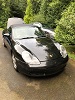
Here's a picture of my temporary wiring setup:
Here's the interface on ignition:
 Ignition.pdf
- (732.88 KiB) Downloaded 56 times
- Start.pdf
- (732.88 KiB) Downloaded 48 times
- Throttle50.pdf
- (732.93 KiB) Downloaded 44 times
-
Boxster EV
- Posts: 434
- Joined: Fri Jul 26, 2019 9:32 pm
- Location: UK
- Has thanked: 35 times
- Been thanked: 26 times
Re: Tesla LDU HV wiring
Okay. So you need to follow the wiring diagram on page one of this viewtopic.php?t=76 thread and most certainly wire-in the encoder. Otherwise you will damage it.
My vague video that might help others in the future:
My vague video that might help others in the future:
Re: Tesla LDU HV wiring
I'm not sure if wiring up the encoder made any difference. Something strange is definitely happening with the signal to the contactors. Perhaps its a soldering issue on the board. Is there a way to troubleshoot to confirm it's a soldering issue?Boxster EV wrote: ↑Sun Mar 12, 2023 7:41 am Okay. So you need to follow the wiring diagram on page one of this viewtopic.php?t=76 thread and most certainly wire-in the encoder. Otherwise you will damage it.
My vague video that might help others in the future:
I'm able to run the motor in manual mode using a pot at 30v. All I want to do is give it full power without blowing the inverter.
-
catphish

- Posts: 955
- Joined: Fri Oct 08, 2021 11:02 pm
- Location: Dorset, UK
- Has thanked: 94 times
- Been thanked: 179 times
Re: Tesla LDU HV wiring
First, before you do anything else, set tripmode=1 (Keep DC switch closed). Any other setting can cause serious damage to the inverter in the event that you hit an overcurrent error.
Next, you're seeing a DC voltage of 468.93. I assume this is wrong, but you need to work out why. Your udcgain seems to be correct (or close enough) but this voltage reading is way too high.
Next, you need to make 100% sure your main contactor is actually closing. Check the wiring here, and test the whole precharge / main contactor setup with the battery disconnected and test that each contactor closes when it should (using a resistance / continuity meter). I'm confused by your screenshots because the "ignition" and "start" documents appear to be identical (ie they're both BEFORE start).
Finally, in your 50% throttle screenshot, the voltage seems to have dropped to near zero. This suggests that something is still very wrong with your HV contactors. If the voltage drops when then the start button is pressed, then most likely your main positive contactor isn't closing, and you're losing high voltage when the precharge contactor opens.
Flashes and bangs from your HV system are very bad. The reason this happened is because you've set udcsw to zero. Please never do this when testing with high voltage. This allowed your main contactor to close without precharging when you attempted to restart, which will have caused a spectacular arc inside your positive main contactor, definitely enough to damage it, and also dangerous for the drive unit itself, though it doesn't seem you did any damage to that if it still works at low voltage.
You say you set the parameters to their defaults, but in the screenshots you seem to be using an LDU config. Did you apply the correct LDU config later? If you were running with defaults, that would explain why everything shut down when you started to apply throttle.bkkona wrote: ↑Thu Mar 09, 2023 5:53 pm I've tried setting udcmin and udcsw to 368 and 330 respectively, as well as 0 and 0. The rest of the parameters are defaulted to those listed here: https://openinverter.org/wiki/Parameters
Next, you're seeing a DC voltage of 468.93. I assume this is wrong, but you need to work out why. Your udcgain seems to be correct (or close enough) but this voltage reading is way too high.
Next, you need to make 100% sure your main contactor is actually closing. Check the wiring here, and test the whole precharge / main contactor setup with the battery disconnected and test that each contactor closes when it should (using a resistance / continuity meter). I'm confused by your screenshots because the "ignition" and "start" documents appear to be identical (ie they're both BEFORE start).
Finally, in your 50% throttle screenshot, the voltage seems to have dropped to near zero. This suggests that something is still very wrong with your HV contactors. If the voltage drops when then the start button is pressed, then most likely your main positive contactor isn't closing, and you're losing high voltage when the precharge contactor opens.
Flashes and bangs from your HV system are very bad. The reason this happened is because you've set udcsw to zero. Please never do this when testing with high voltage. This allowed your main contactor to close without precharging when you attempted to restart, which will have caused a spectacular arc inside your positive main contactor, definitely enough to damage it, and also dangerous for the drive unit itself, though it doesn't seem you did any damage to that if it still works at low voltage.
-
catphish
- Posts: 955
- Joined: Fri Oct 08, 2021 11:02 pm
- Location: Dorset, UK
- Has thanked: 94 times
- Been thanked: 179 times
Re: Tesla LDU HV wiring
To be specific, this situation means the precharge contactor is opening, but the main contactor is never closing. Check the wiring to all 3 contactors, particularly the main positive contactor.
Please fix your udcsw and tripmode values before you do any damage though!
I'd suggest making sure the contactors all work with your low voltage power supply before attempting to connect the high voltage supply again. Focus your attention on whether the positive main contactor is closing when you press the start switch.
Re: Tesla LDU HV wiring
Thanks for the thorough reply. I'm using an LDU, are those the wrong default parameters? Which parameters should I be using?catphish wrote: ↑Tue Mar 14, 2023 12:55 am You say you set the parameters to their defaults, but in the screenshots you seem to be using an LDU config. Did you apply the correct LDU config later? If you were running with defaults, that would explain why everything shut down when you started to apply throttle.
Re: Tesla LDU HV wiring
How do I do this? I don't see an option for a numerical input. Do you mean to select the first option in the drop down menu?
How can I test that the contactor is closing using my multimeter?catphish wrote: ↑Tue Mar 14, 2023 12:55 am Next, you need to make 100% sure your main contactor is actually closing. Check the wiring here, and test the whole precharge / main contactor setup with the battery disconnected and test that each contactor closes when it should (using a resistance / continuity meter). I'm confused by your screenshots because the "ignition" and "start" documents appear to be identical (ie they're both BEFORE start).
-
catphish
- Posts: 955
- Joined: Fri Oct 08, 2021 11:02 pm
- Location: Dorset, UK
- Has thanked: 94 times
- Been thanked: 179 times
Re: Tesla LDU HV wiring
You should be using parameters designed for an LDU. These can be found at https://openinverter.org/parameters/view.html?id=16
In fact these ARE the parameters you appear to be using, but I was confused because in your post you said you were using the default parameters listed at https://openinverter.org/wiki/Parameters which are totally different.
-
catphish
- Posts: 955
- Joined: Fri Oct 08, 2021 11:02 pm
- Location: Dorset, UK
- Has thanked: 94 times
- Been thanked: 179 times
Re: Tesla LDU HV wiring
The correct mode is called "DcSwOn". This keeps the contactors closed during a fault, which sounds strange, but is the safest option for protecting your hardware.
1) Disconnect ALL high voltage cables from all contactors.
2) Temporarily set udcsw to zero to allow it to switch the contactors with no voltage present
3) Put multimeter into continuity (buzz) mode, and check A1->A2 of each contactor.
When first powered on, only the precharge contactor should conduct, then after pressing the start button, only the main contactor should conduct. Assuming the negative contactor is permanently powered, that should conduct all the time.
Test the resistance of your precharge resistor too.
Re: Tesla LDU HV wiring
I appreciate you! I'll report back here.catphish wrote: ↑Tue Mar 14, 2023 1:36 am The correct mode is called "DcSwOn". This keeps the contactors closed during a fault, which sounds strange, but is the safest option for protecting your hardware.
1) Disconnect ALL high voltage cables from all contactors.
2) Temporarily set udcsw to zero to allow it to switch the contactors with no voltage present
3) Put multimeter into continuity (buzz) mode, and check A1->A2 of each contactor.
When first powered on, only the precharge contactor should conduct, then after pressing the start button, only the main contactor should conduct. Assuming the negative contactor is permanently powered, that should conduct all the time.
Test the resistance of your precharge resistor too.
Re: Tesla LDU HV wiring
I realized my board came with parameters that are different from the ones listed above while troubleshooting, which ended up with a hodge-podge of parameters. One of which was ocurlim. Thank God I found this viewtopic.php?t=76&start=275 . I thought I cooked the inverter before I realized the solution to my new found Stop Overcurrent error was due to a simple sign flip from - to +.catphish wrote: ↑Tue Mar 14, 2023 1:30 am You should be using parameters designed for an LDU. These can be found at https://openinverter.org/parameters/view.html?id=16
In fact these ARE the parameters you appear to be using, but I was confused because in your post you said you were using the default parameters listed at https://openinverter.org/wiki/Parameters which are totally different.
Re: Tesla LDU HV wiring
I checked the continuity on each contactor and resistor. They all checked out. I changed the mode to DcSwOn as well. When I power on, BOTH main and pre-charge contactors close. On start, they both open. So it seems the pre-charge contactor is performing as it should but the main is just mimicking the pre-charge. I've attached my current parameters in case there's something there that explains this behavior.catphish wrote: ↑Tue Mar 14, 2023 1:36 am The correct mode is called "DcSwOn". This keeps the contactors closed during a fault, which sounds strange, but is the safest option for protecting your hardware.
1) Disconnect ALL high voltage cables from all contactors.
2) Temporarily set udcsw to zero to allow it to switch the contactors with no voltage present
3) Put multimeter into continuity (buzz) mode, and check A1->A2 of each contactor.
When first powered on, only the precharge contactor should conduct, then after pressing the start button, only the main contactor should conduct. Assuming the negative contactor is permanently powered, that should conduct all the time.
Test the resistance of your precharge resistor too.
- Updated.pdf
- (729.27 KiB) Downloaded 62 times
-
Boxster EV
- Posts: 434
- Joined: Fri Jul 26, 2019 9:32 pm
- Location: UK
- Has thanked: 35 times
- Been thanked: 26 times
Re: Tesla LDU HV wiring
What are you using for a 12v power supply?
If it’s a car battery are you sure it’s fully charged?
If it’s a car battery are you sure it’s fully charged?
Re: Tesla LDU HV wiring
I'm using a power supplyBoxster EV wrote: ↑Tue Mar 14, 2023 7:47 pm What are you using for a 12v power supply?
If it’s a car battery are you sure it’s fully charged?
-
catphish
- Posts: 955
- Joined: Fri Oct 08, 2021 11:02 pm
- Location: Dorset, UK
- Has thanked: 94 times
- Been thanked: 179 times
Re: Tesla LDU HV wiring
Certainly sounds like you've found the problem. I don't have an obvious explanation though.bkkona wrote: ↑Tue Mar 14, 2023 7:22 pm When I power on, BOTH main and pre-charge contactors close. On start, they both open. So it seems the pre-charge contactor is performing as it should but the main is just mimicking the pre-charge. I've attached my current parameters in case there's something there that explains this behavior.
Make sure you're using the latest software version. It 100% should not be activating the main contactor switched ground output before the start button is pressed.
-
Boxster EV
- Posts: 434
- Joined: Fri Jul 26, 2019 9:32 pm
- Location: UK
- Has thanked: 35 times
- Been thanked: 26 times
Re: Tesla LDU HV wiring
Humour us and try with a charged 12v car battery for low voltage side and per Catphish upgrade to sine firmware v5.20r
Edit: these are my parameters working with a base LDU and sine firmware 5.20r
Edit: these are my parameters working with a base LDU and sine firmware 5.20r
Re: Tesla LDU HV wiring
I just updated the firmware to version 5.20r and inputted the parameters you shared. Still no fix. I have yet to try a 12v car battery (I don't have one on hand) but I have low confidence this is the issue.Boxster EV wrote: ↑Tue Mar 14, 2023 9:42 pm Humour us and try with a charged 12v car battery for low voltage side and per Catphish upgrade to sine firmware v5.20r
Edit: these are my parameters working with a base LDU and sine firmware 5.20r
params.json
-
Boxster EV
- Posts: 434
- Joined: Fri Jul 26, 2019 9:32 pm
- Location: UK
- Has thanked: 35 times
- Been thanked: 26 times
Re: Tesla LDU HV wiring
Please also post a video of your whole set-up including the process of going through the pre-charge cycle and spot values changing.
Re: Tesla LDU HV wiring
Please find video here: https://we.tl/t-M0ipMMB1ELBoxster EV wrote: ↑Wed Mar 15, 2023 8:23 am Please also post a video of your whole set-up including the process of going through the pre-charge cycle and spot values changing.
Attached below you'll find the ignition and start spot values, as well as my current parameters.
-
Boxster EV
- Posts: 434
- Joined: Fri Jul 26, 2019 9:32 pm
- Location: UK
- Has thanked: 35 times
- Been thanked: 26 times
Re: Tesla LDU HV wiring
I don’t understand what’s happening. The main contactor shouldn’t close when you apply 12v during pre-charge, but it seems to do so in your video. It should only close when pin 23 has 12v momentarily applied to enter into run mode. There is either an issue with your LV wiring, or something awry with the board.
You might need some specialist support that can be accessed here:
https://openinverter.org/shop/index.php ... duct_id=65
You might need some specialist support that can be accessed here:
https://openinverter.org/shop/index.php ... duct_id=65
-
asavage

- Posts: 329
- Joined: Sat May 14, 2022 10:57 pm
- Location: Oak Harbor, Washington, USA
- Has thanked: 278 times
- Been thanked: 103 times
- Contact:
Re: Tesla LDU HV wiring
I can't tell where the leads that go off-screen go, they need labeling in this shot. I mean, I can see some components, but I can only see their wiring in relation to each other, not to the what feeds them or what they power.
While I'm not certain, I fear that you may have your negative contactor's HV reversed. You always want the more-positive lead to be on screw terminal A1, which means that on the negative contactor, the lead to your battery negative should be on A2 of that contactor.
TE's datasheet for the EVCnnn series is explicit about this:
- TE's EVC135 reverse current lifecycle warning
In ideal circumstances, you're never making/breaking the contacts with any significant load, and the polarity issue is nil, but it's still good design practice to wire 'em the way the mfgr recommends, and TE builds a lot of EV components . . .
None of which has anything to do with your system's other issues, but this caught my eye.
---
Next, the LV contactors wiring from https://openinverter.org/forum/viewtopic.php?p=515#p515
Boxster EV wrote: ↑Wed Mar 15, 2023 8:50 pm There is either an issue with your LV wiring, or something awry with the board