Tesla LDU board contactor control pins current sinking
Posted: Sat May 15, 2021 11:30 pm
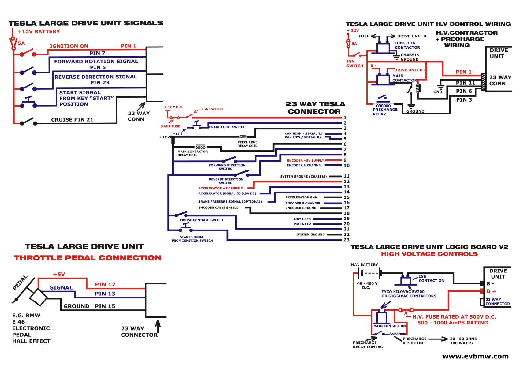
I'm currently sourcing the contactors for the HV setup and am curious about the current sinking ability of pin 6 on the LDU board. In the diagram posted on the LDU support forum (download/file.php?id=680&mode=view) the control pin (6) is hooked up directly to the contactor coil. Now on the other hand the current image on the wiki shows an intermediate relay driven from pin 6 and driving the contactor coil (https://openinverter.org/wiki/images/b/ ... iagram.png).
So I'm interested in knowing what the control pin is designed to sink; the pick-up current for e.g. https://www.gigavac.com/sites/default/f ... t/gx16.pdf is as high as 3.8A.
On a related note, with the ignition contactor drawing a steady 0.64A (see Gigavac) it seems the contactors eat as much as 3.8+0.64=4.44A of the 5A budget limited by the shared 5A fuse. I have seen the control board run over 0.56A on the bench, does it make sense to have separate fuses for the contactor coils?