Page 4 of 37
Re: Prius Gen2 adapter board development thread
Posted: Thu Apr 30, 2020 7:06 pm
by johu
Done

Some changes in pin assignment:
- GIVA - to level shifter 1
- MIVA - another input to level shifter 1
- GIWA - to level shifter 2
- MIVA - another input to level shifter 2
- VH - udc input
- MIVT - tmphs input
- MFIV - desat input
- CPWM - PWM2_N for charging
- MUU - PWM1
- MVU - PWM2
- MWU - PWM3
- GINV and GCNV and GND - ground everything here
- Encoder channel B/Resolver S3
- GND/Resolver center point S1S4
- Encoder channel A or single channel input/Resolver S2
- Resover excitation R1
- Resover excitation R2
- 5V output
- Throttle Input (0-3.3V)
- 2nd Throttle Input (0-3.3V)
- Start input (12V)
- Brake Input (12V)
- Forward (12V)
- Reverse (12V)
- Motor Temperature Input -
- Motor Temperature Input +
- DC contactor output
- Precharge Output
- CANL
- CANH
- GND
- 12V
I use the TDA2822 in bridge mode now, meaning it can do true bipolar output -> Can generate 9V p-p from 5V supply rail. And that means I could remove the boost converter. I also removed the over current comparator since the Prius HW takes care of that. ABZ encoder is no longer supported, don't know of anyone who ever used it.
The only unknown is the "MFIV" fault output from the inverter. Don't know yet what it outputs as "good" and "bad". Right now I'm assuming it outputs 12V for bad and 0V for good.
Re: Prius Gen2 adapter board development thread
Posted: Thu Apr 30, 2020 7:28 pm
by konstantin8818
Jack Bauer wrote: ↑Sun Mar 01, 2020 1:15 pm
Can never have too many boards:)
...so already have got two and definitely going to buy third one
Re: Prius Gen2 adapter board development thread
Posted: Thu Apr 30, 2020 7:35 pm
by SciroccoEV
johu wrote: ↑Thu Apr 30, 2020 7:06 pm
The only unknown is the "MFIV" fault output from the inverter. Don't know yet what it outputs as "good" and "bad". Right now I'm assuming it outputs 12V for bad and 0V for good.
From the Prius manual...
Re: Prius Gen2 adapter board development thread
Posted: Thu Apr 30, 2020 8:15 pm
by johu
SciroccoEV wrote: ↑Thu Apr 30, 2020 7:35 pm
From the Prius manual...
So it means
normal - 5.4V to 7.4V
abnormal - 2V to 3V
In other word <3V abnormal ?
Not a very nice logic level...
Re: Prius Gen2 adapter board development thread
Posted: Thu Apr 30, 2020 8:21 pm
by SciroccoEV
johu wrote: ↑Thu Apr 30, 2020 8:15 pm
In other word <3V abnormal ?
Not a very nice logic level...
I've found that the stated voltages don't necessarily match up with reality on the bench.
Perhaps they do when feeding impedance of the OEM ECU.
Re: Prius Gen2 adapter board development thread
Posted: Fri May 01, 2020 2:20 am
by ZooKeeper
johu wrote: ↑Thu Apr 30, 2020 7:06 pm
Done
<<<<<<< = Much Drooling.....

Re: Prius Gen2 adapter board development thread
Posted: Fri May 01, 2020 12:12 pm
by RetroZero
Yes, much drooling. Awesome job (again) Johu! Will see locally how much to make up 5 (for testing), and delay times?
Re: Prius Gen2 adapter board development thread
Posted: Fri May 01, 2020 12:47 pm
by johu
Easy, easy
will get some made at JLC and test them, then will publish the design.
Did a little testing on my inverter, with just 24V DC voltage. So 25mV per A of phase current is confirmed - measured 64A RMS with the clamp meter and getting 1.7V RMS on the sensor output. You can see it's not quite sinusoidal, I think thats because the inverter behaves weird at low sine amplitudes. Still hoping higher voltages to mitigate this.
MFIV signal is 7.2V indeed but I couldn't provoke over current with my worn out lead batteries

Re: Prius Gen2 adapter board development thread
Posted: Fri May 01, 2020 2:11 pm
by johu
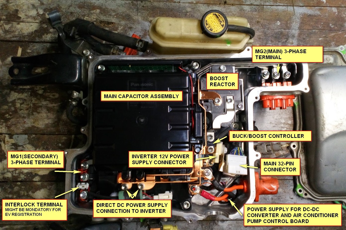
I am about to order some parts. Can anyone tell me the part number of the 2-pole "inverter 12V power supply connector" (next to 32-pin signal plug):
Re: Prius Gen2 adapter board development thread
Posted: Fri May 01, 2020 5:44 pm
by RetroZero
Sorry, looked from connecter I have with reference 11717. No luck, will check tomorrow again if no on can come to rescue
Re: Prius Gen2 adapter board development thread
Posted: Fri May 01, 2020 5:57 pm
by arber333
I recommend you search for them, but in the meantime you find some PVC material and cut and file it to shape. Then drill holes for bolts and two centraly positioned holes for two cables you intend to use. You glue/seal DC cables onto this plate by means of black auto glass sealant, of course on the inside. You get nice flat grommet secure from moisture etc.
I have done this many times and it can only be removed intentionally.
Re: Prius Gen2 adapter board development thread
Posted: Fri May 01, 2020 6:52 pm
by johu
Ah but you mean for the HV DC bus? I meant the little 12V input.
Re: Prius Gen2 adapter board development thread
Posted: Fri May 01, 2020 6:57 pm
by SciroccoEV
It's not exactly an expensive connector to replace, I'd just buy a matching plug and socket.
Re: Prius Gen2 adapter board development thread
Posted: Fri May 01, 2020 7:35 pm
by konstantin8818
SciroccoEV wrote: ↑Fri May 01, 2020 6:57 pm
It's not exactly an expensive connector to replace, I'd just buy a matching plug and socket.
My first thought exactly
Why bother with OEM when you can replace it with any aftermarket. I consider I'm lucky to have piece of OEM harness with sealant.
Anyway I've got number 11717 on my connector, so google shows it correctly: 90980-11717
Re: Prius Gen2 adapter board development thread
Posted: Fri May 01, 2020 7:37 pm
by ZooKeeper
post deleted
Re: Prius Gen2 adapter board development thread
Posted: Fri May 01, 2020 8:27 pm
by RetroZero
Good find Konstantin8818.
Re: Prius Gen2 adapter board development thread
Posted: Fri May 01, 2020 8:30 pm
by RetroZero
johu wrote: ↑Fri May 01, 2020 12:47 pm
Easy, easy
will get some made at JLC and test them, then will publish the design.
Will leave you to it then. Just let me know when I too can become a proud member of an openinverter board

..

Re: Prius Gen2 adapter board development thread
Posted: Sat May 02, 2020 5:32 am
by konstantin8818
johu wrote: ↑Fri May 01, 2020 12:47 pm
Easy, easy
will get some made at JLC and test them, then will publish the design.
It's going to be a loooong waiting. My blue pills ordered from China lie somewhere for over one and a half month already

Re: Prius Gen2 adapter board development thread
Posted: Sat May 02, 2020 6:40 am
by RetroZero
I have located another company, in my Town that does prototype pcb's. I know it will be 'expensive' compared with JLC, but I could ask around? However, if Johu prefers to have them built and tested through known channels, I understand too.
Re: Prius Gen2 adapter board development thread
Posted: Sat May 02, 2020 6:52 am
by Jack Bauer
I have encountered no delays with JLC. about ten days for smd board builds.
Re: Prius Gen2 adapter board development thread
Posted: Sat May 02, 2020 7:16 am
by RetroZero
Thanks for info.

Re: Prius Gen2 adapter board development thread
Posted: Sat May 02, 2020 9:45 am
by konstantin8818
Jack Bauer wrote: ↑Sat May 02, 2020 6:52 am
I have encountered no delays with JLC. about ten days for smd board builds.
Oh, that is a good news. We'll hope for the best.
Re: Prius Gen2 adapter board development thread
Posted: Mon May 04, 2020 7:25 am
by RetroZero
I might have to go locking up a planet gear set whilst I await 'the cure'. Will post in the transaxle post as I go....
Re: Prius Gen2 adapter board development thread
Posted: Mon May 04, 2020 5:34 pm
by konstantin8818
RetroZero wrote: ↑Mon May 04, 2020 7:25 am
I might have to go locking up a planet gear set whilst I await 'the cure'. Will post in the transaxle post as I go....
"the cure" is a simple chunk of metal produced with the lathe. All you need is do some measurements maybe with a micrometer, and a good lathe operator. Unfortunately, I went by the way of MGR, and have got no free money to purchase prius gearabox to disassmle it. Yet I've got micrometer and a good lathe operator=)
Re: Prius Gen2 adapter board development thread
Posted: Mon May 04, 2020 5:40 pm
by johu
Order at JLCPCB placed
I have made some small changes: solder jumpers for optional encoder pull-up resistors (thanks Damien) and corrected inverter fault detection.
EDIT: and I created a logo

 ..
.. 
