Page 4 of 37
Re: Prius Gen2 adapter board development thread
Posted: Wed Apr 29, 2020 6:35 am
by RetroZero
Thanks everyone - I realise I have been mixing things up...to make things worse.
So PWM pins on adapter board are OUTPUTS of 3.3v that require an amplification to 12v (by ULN2003). Adapterboard to MUU, MVU, MWU for MG2.
At the same time, the Current values INPUTS on adapterboard need to be corrected from 15v p-p(bi-polar) down to 0v - 3.3v.
The current values are connected in parralel, MIVA and MIWA for MG2, via the op-amp circuit before arriving at the adapter board II1
A duplicate is required for MG1 (for charging purposes)
I hope I got it now.
Re: Prius Gen2 adapter board development thread
Posted: Wed Apr 29, 2020 8:22 am
by RetroZero
I assume the "add-ons" for PWM signals, current sensor reading and blending are going to be resolved with new board. I am about to order Johanes's V3 board, along with necessary resistors, ULN2003, strip boards etc, and 'try' to create these add-ons....
I have a registered company here in France, so I could also ask for quotes to create the new board here, if Johannes is close to having the schematics, instead of me designing and building something 'a little beyond my skills'....no pressure, I am happy to stumble on if we are still in early stages of board fabrication..
Re: Prius Gen2 adapter board development thread
Posted: Wed Apr 29, 2020 5:01 pm
by RetroZero
You guys have been very patient with me.
Just in case it will be a while before a board can be built for testing, and after spending quite a few hours, again, I hope I have worked out this "bipolar-to-unipolar-with-AD822 circuit". Still a few blanks to fill in...if anyone has energy left - I appologise for tier 4 questions again.
Re: Prius Gen2 adapter board development thread
Posted: Wed Apr 29, 2020 5:02 pm
by RetroZero
oops, attachement not in link..
Re: Prius Gen2 adapter board development thread
Posted: Wed Apr 29, 2020 6:12 pm
by johu
Schematic done, does anyone feel like routing this out in KiCAD?
I've included a footprint for the ModICE connector but I believe there is a better one in KiCAD.
EDIT: I have started layout, therefor removed the Eagle file here.
Re: Prius Gen2 adapter board development thread
Posted: Thu Apr 30, 2020 4:38 am
by kiwifiat
SciroccoEV wrote: ↑Tue Apr 28, 2020 8:04 am
kiwifiat wrote: ↑Tue Apr 28, 2020 12:32 am
So we have the transfer function but not the limits, it isn't possible to design a suitable conditioning circuit without knowledge of the output range.
Do you know what voltage the output saturates at? Are they 15V p-p or 20V p-p?
The linear output range of the current sensors likely exceeds the over current shutdown point of the power module.
Damien has performed short circuit tests to determine the approximate over current shutdown point.
Do I have to connect the dots for you?
I follow your logic. I found a reference here:
http://isopack.blogspot.com/2015/02/tur ... silly.html and was hoping you might be able to corroborate the 400A rating of the MG2 sensors which would put them at 20V p-p. Certainly makes getting the level shift circuitry spot on. I haven't been able to locate any actual ratings for the gen2 current sensors in any of the Oak Ridge Lab reports sadly.
Re: Prius Gen2 adapter board development thread
Posted: Thu Apr 30, 2020 4:57 am
by kiwifiat
johu wrote: ↑Tue Apr 28, 2020 5:22 am
I would assume +/-600A or +/-15V to be a sensible range. So 30V p-p. FOC doesn't need that good SNR but I agree saturation would probably trigger a current limit.
EDIT: modified your design for roughly +/-15V and two inputs
You know what they say about assumptions! Regarding current sensor noise the engineering teams that designed the Honda IMA, Gen1 Leaf, Volt/Ampera inverters all thought it was important enough to include 3 current sensors in their designs as did the designer of the Lebowski controller.
Cost accountants getting in the way of engineering excellence. Sure we are stuck with 2 current sensors in the Toyota inverters and yes they run just fine. I think it is worth the effort to get the current data going in to the controller as accurate and with highest precision possible and to do that we need to know their maximum rating. Maybe Damien will come to our rescue.
I like the way you eliminated the precision voltage reference on the level shift schematic.
Re: Prius Gen2 adapter board development thread
Posted: Thu Apr 30, 2020 6:46 am
by RetroZero
Nice one Johu, but KiCAD bayond my scope. Let me know if you're interested in me getting confidentiality agreement signed with local company SMEE, and getting quote for making boards in France based on schematics.
Re: Prius Gen2 adapter board development thread
Posted: Thu Apr 30, 2020 8:32 am
by johu
kiwifiat wrote: ↑Thu Apr 30, 2020 4:57 am
You know what they say about assumptions! Regarding current sensor noise the engineering teams that designed the Honda IMA, Gen1 Leaf, Volt/Ampera inverters all thought it was important enough to include 3 current sensors in their designs as did the designer of the Lebowski controller.
Well I didn't do much engineering excellence on the Leaf dropin board either (just a simple voltage divider) and it works just fine

The Lebowski is special as it runs sensorless control which we do not.
If it turns out a huge problem it's easily solved with different resistor values.
RetroZero wrote: ↑Thu Apr 30, 2020 6:46 am
Nice one Johu, but KiCAD bayond my scope. Let me know if you're interested in me getting confidentiality agreement signed with local company SMEE, and getting quote for making boards in France based on schematics.
I ain't signin no agreement

I'll route out the board in Eagle today and/or tomorrow and make it public.
Re: Prius Gen2 adapter board development thread
Posted: Thu Apr 30, 2020 9:20 am
by RetroZero
Sorry, not you. The company that makes the boards here in France. Wouldn't want them to go using it for anyone else. I have found out, the company Advantics, is based not too far from me. They might be creating there circuit boards locally, and might be using SMEE..
Re: Prius Gen2 adapter board development thread
Posted: Thu Apr 30, 2020 7:06 pm
by johu
Done
Some changes in pin assignment:
- GIVA - to level shifter 1
- MIVA - another input to level shifter 1
- GIWA - to level shifter 2
- MIVA - another input to level shifter 2
- VH - udc input
- MIVT - tmphs input
- MFIV - desat input
- CPWM - PWM2_N for charging
- MUU - PWM1
- MVU - PWM2
- MWU - PWM3
- GINV and GCNV and GND - ground everything here
- Encoder channel B/Resolver S3
- GND/Resolver center point S1S4
- Encoder channel A or single channel input/Resolver S2
- Resover excitation R1
- Resover excitation R2
- 5V output
- Throttle Input (0-3.3V)
- 2nd Throttle Input (0-3.3V)
- Start input (12V)
- Brake Input (12V)
- Forward (12V)
- Reverse (12V)
- Motor Temperature Input -
- Motor Temperature Input +
- DC contactor output
- Precharge Output
- CANL
- CANH
- GND
- 12V
I use the TDA2822 in bridge mode now, meaning it can do true bipolar output -> Can generate 9V p-p from 5V supply rail. And that means I could remove the boost converter. I also removed the over current comparator since the Prius HW takes care of that. ABZ encoder is no longer supported, don't know of anyone who ever used it.
The only unknown is the "MFIV" fault output from the inverter. Don't know yet what it outputs as "good" and "bad". Right now I'm assuming it outputs 12V for bad and 0V for good.
Re: Prius Gen2 adapter board development thread
Posted: Thu Apr 30, 2020 7:28 pm
by konstantin8818
Jack Bauer wrote: ↑Sun Mar 01, 2020 1:15 pm
Can never have too many boards:)
...so already have got two and definitely going to buy third one
Re: Prius Gen2 adapter board development thread
Posted: Thu Apr 30, 2020 7:35 pm
by SciroccoEV
johu wrote: ↑Thu Apr 30, 2020 7:06 pm
The only unknown is the "MFIV" fault output from the inverter. Don't know yet what it outputs as "good" and "bad". Right now I'm assuming it outputs 12V for bad and 0V for good.
From the Prius manual...
Re: Prius Gen2 adapter board development thread
Posted: Thu Apr 30, 2020 8:15 pm
by johu
SciroccoEV wrote: ↑Thu Apr 30, 2020 7:35 pm
From the Prius manual...
So it means
normal - 5.4V to 7.4V
abnormal - 2V to 3V
In other word <3V abnormal ?
Not a very nice logic level...
Re: Prius Gen2 adapter board development thread
Posted: Thu Apr 30, 2020 8:21 pm
by SciroccoEV
johu wrote: ↑Thu Apr 30, 2020 8:15 pm
In other word <3V abnormal ?
Not a very nice logic level...
I've found that the stated voltages don't necessarily match up with reality on the bench.
Perhaps they do when feeding impedance of the OEM ECU.
Re: Prius Gen2 adapter board development thread
Posted: Fri May 01, 2020 2:20 am
by ZooKeeper
johu wrote: ↑Thu Apr 30, 2020 7:06 pm
Done
<<<<<<< = Much Drooling.....

Re: Prius Gen2 adapter board development thread
Posted: Fri May 01, 2020 12:12 pm
by RetroZero
Yes, much drooling. Awesome job (again) Johu! Will see locally how much to make up 5 (for testing), and delay times?
Re: Prius Gen2 adapter board development thread
Posted: Fri May 01, 2020 12:47 pm
by johu
Easy, easy
will get some made at JLC and test them, then will publish the design.
Did a little testing on my inverter, with just 24V DC voltage. So 25mV per A of phase current is confirmed - measured 64A RMS with the clamp meter and getting 1.7V RMS on the sensor output. You can see it's not quite sinusoidal, I think thats because the inverter behaves weird at low sine amplitudes. Still hoping higher voltages to mitigate this.
MFIV signal is 7.2V indeed but I couldn't provoke over current with my worn out lead batteries

Re: Prius Gen2 adapter board development thread
Posted: Fri May 01, 2020 2:11 pm
by johu
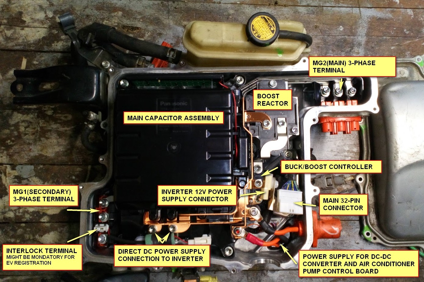
I am about to order some parts. Can anyone tell me the part number of the 2-pole "inverter 12V power supply connector" (next to 32-pin signal plug):
Re: Prius Gen2 adapter board development thread
Posted: Fri May 01, 2020 5:44 pm
by RetroZero
Sorry, looked from connecter I have with reference 11717. No luck, will check tomorrow again if no on can come to rescue
Re: Prius Gen2 adapter board development thread
Posted: Fri May 01, 2020 5:57 pm
by arber333
I recommend you search for them, but in the meantime you find some PVC material and cut and file it to shape. Then drill holes for bolts and two centraly positioned holes for two cables you intend to use. You glue/seal DC cables onto this plate by means of black auto glass sealant, of course on the inside. You get nice flat grommet secure from moisture etc.
I have done this many times and it can only be removed intentionally.
Re: Prius Gen2 adapter board development thread
Posted: Fri May 01, 2020 6:52 pm
by johu
Ah but you mean for the HV DC bus? I meant the little 12V input.
Re: Prius Gen2 adapter board development thread
Posted: Fri May 01, 2020 6:57 pm
by SciroccoEV
It's not exactly an expensive connector to replace, I'd just buy a matching plug and socket.
Re: Prius Gen2 adapter board development thread
Posted: Fri May 01, 2020 7:35 pm
by konstantin8818
SciroccoEV wrote: ↑Fri May 01, 2020 6:57 pm
It's not exactly an expensive connector to replace, I'd just buy a matching plug and socket.
My first thought exactly
Why bother with OEM when you can replace it with any aftermarket. I consider I'm lucky to have piece of OEM harness with sealant.
Anyway I've got number 11717 on my connector, so google shows it correctly: 90980-11717
Re: Prius Gen2 adapter board development thread
Posted: Fri May 01, 2020 7:37 pm
by ZooKeeper
post deleted