Page 4 of 4
Re: MLBevo Charger- 11kw & 22kw Info
Posted: Sun Aug 03, 2025 12:03 pm
by modellfan
I connected it according to the infos in the wiki. My charger needs just one can bus connected as it is 11kw MLBevo . Yes the webinterface is for the zombie to see the Infos while charging
Re: MLBevo Charger- 11kw & 22kw Info
Posted: Sat Dec 06, 2025 2:01 pm
by m.art.y
modellfan wrote: ↑Sat Aug 02, 2025 9:51 am
Last night, I coppied over the state machine from teensy (except the wrong conditions) and also the preset values. Now it is working.
Hi, is it working on a Zombie? Does the charger needs configuring and how did you do it? Did you use original charging socket and where did you connect PP/CP wires from socket?
Re: MLBevo Charger- 11kw & 22kw Info
Posted: Sat Dec 06, 2025 2:20 pm
by m.art.y
LRBen wrote: ↑Sun Feb 25, 2024 9:38 am
Finally managed to port the teensy script over to Zombie and had my Cayenne charger working in the vehicle yesterday.
Does the charger need to be configured first? How?
Re: MLBevo Charger- 11kw & 22kw Info
Posted: Sat Dec 06, 2025 10:00 pm
by LRBen
m.art.y wrote: ↑Sat Dec 06, 2025 2:20 pm
Does the charger need to be configured first? How?
It needed to be coded with PIWIS or ODIS. Can't remember exactly now but there have been allot of posts about it.
Re: MLBevo Charger- 11kw & 22kw Info
Posted: Mon Dec 08, 2025 12:05 am
by modellfan
Did you even have a look in the wiki ? There is described to which pin pp and cp goes and how to configure it. I used vcds. With my updated code i even got a green led when charging
https://youtu.be/iWVAdwRuo7c?si=rHujVz16zNSYd6nj
Re: MLBevo Charger- 11kw & 22kw Info
Posted: Mon Dec 08, 2025 6:34 am
by m.art.y
modellfan wrote: ↑Mon Dec 08, 2025 12:05 am
With my updated code i even got a green led when charging.
Sorry info here is difficult to understand between charger varieties. Just looking for a proven solution or step by step guide. Could you upload your detailed tutorial video?
Re: MLBevo Charger- 11kw & 22kw Info
Posted: Mon Dec 08, 2025 5:58 pm
by m.art.y
Maybe somebody could give some insight if it would be possible to run two 11 kw chargers from the same charging socket and what would it take? Would Zombie be able to run two of those at the same time?
Re: MLBevo Charger- 11kw & 22kw Info
Posted: Tue Dec 23, 2025 11:52 pm
by modellfan
I am not sure , if they won’t interfere on CP and PP . From zombie side with adjustments of code I have no doubts. Main problem would be , that CAN handling of standard zombie does not differentiate between two CAN busses.
Re: MLBevo Charger- 11kw & 22kw Info
Posted: Wed Dec 24, 2025 8:32 am
by m.art.y
The reason I'm looking at those chargers is because I need full 22 kw of charging power. So it's either 2x 11 kw ones or there is a 22 kw charger with part numbers 9J1915681AD &
9J1915681AH. It has two separate 3 phase connectors but I'm not sure if they both share only one CP and PP signal or if there is a pair of those coming from each charging socket. Anybody has any info on that? Also it's made by Meta and not Kostal like most of the other chargers. I hope it's still compatible with the same code? Thanks

Re: MLBevo Charger- 11kw & 22kw Info
Posted: Fri Dec 26, 2025 9:37 pm
by modellfan
Here you go. Please check the wiki against it.
https://youtu.be/MoXbGSCYNWA?si=QYTCmzrC3DV4Rrlu
Merry Christmas!
Re: MLBevo Charger- 11kw & 22kw Info
Posted: Wed Jan 07, 2026 1:09 pm
by Mitchy
Great video!
Would you happen to have a CanLog of a charge session?
I've begun updating some of the documentation and wiring diagrams, As I've finally got to the stage of installing and actually charging with it using Zombie. Been trying to align whatever values/datatypes between each. Since I've made some mistakes in some of the conversion/scaling.
For some reason I'm getting capped at 3500w
Even though my lvl2 cable is detected at 40A (240V)
I'm seeing the following values:
0x488 - HVLM_06 - HVLM_MaxLadeLeistung: 3500w
0x53C - HVLM_04 - HVLM_HVEM_MaxLeistung: 3500w
0x67E - LAD_02 - LAD_MaxLadLeistung_HV: 3500w
I suspect that it was a previous charge limitation that was entered via the charge scheduling system.
If you have VCDS, I think the charge limitation values below cross reference to the CAN messages above:
IDE08639 - max. loading power
ENG125868 - maximum_charging_power_battery_charger
ENG250367 - maximum_power_hvem
I should hopefully know more tonight, as until last night I was only testing with 120v.
Going to connect up with ODIS / PIWIS to see what other runtime values I see... And if any other errors are generated.
Re: MLBevo Charger- 11kw & 22kw Info
Posted: Sun Jan 11, 2026 2:19 am
by modellfan
Nope no CAN log. But did you take a look at my code ?
https://github.com/Modellfan/Zombie-Sla ... harger.cpp
I used yours as a base. Restructured the software architecture and fixed some bugs. With this I get a green led and 11KW. Should be copy and paste more or less.
Edit: this is my original work repository which is a fork of yours. Going to history you should be able to see every single change I did
https://github.com/Modellfan/Stm32-vcu_ ... harger.cpp
Re: MLBevo Charger- 11kw & 22kw Info
Posted: Thu Jan 15, 2026 1:40 am
by Mitchy
I'm using a fork of your fork.

Not much has changed though.
I'm using a 2518FD SPI CAN channel added into zombie. So my Can-Send is slightly different but other than that it's pretty much the same.
I'm starting to think that Component Protection is tripped and causing a charge reduction.
I should say... I know component protection is tripped

Since I get the DTC for it. (U11010)
Although I'm unable to find anything that references a reduction in power output with it active.
I believe you have more faults active as your charger has a later software rev.
I started with 0070, but updated it to 0089 tonight. After which I was greeted with similar faults.
Have you been using the charger much in operation? I'm wondering if I tripped the Component protection by a timeout, or if I sent a misguided command and it wanted to call back to the gateway.
I'm also on a single phase. But I didn't attempt to change the Current from 63A to 32A (like you have set) but unsure if you're getting 11kw from a single phase connection?
Charger starts up with a single phase/module, max of ~8A output, After a few minutes you can hear it load balance over to the 2nd module, whereby each split ~4.1A
Input AC current is ~15.7A @ 244 V
If you do connect up via CAN sometime, it'll be interesting if you have the Component Protection active.
CAN ID: 0x17F00044 - It's the first bit
If it activates - and you see a reduction - It may be game over for this type of charger.
The older units do not seem to have component protection, so there still may be hope for them.
Re: MLBevo Charger- 11kw & 22kw Info
Posted: Thu Jan 15, 2026 1:23 pm
by jrbe
When looking at charger info over VCDS are there any that have missing info? I'd guess there is a "limp" mode when data is missing to be able to drive full power safely. Charger socket temp, BMS charge amperage request, etc. May be able to work what's missing and forcing the reduced charge level this way.
Re: MLBevo Charger- 11kw & 22kw Info
Posted: Fri Jan 16, 2026 11:25 pm
by modellfan
When I have the battery back in the car , I will test it. I get also faults cause my temp sensors are not configured correctly. In Germany we have 3x 16A for 11kw . This might be a difference. Please send a screenshot of the dtc you get. What the link of your fork ?
Re: MLBevo Charger- 11kw & 22kw Info
Posted: Sun Jan 25, 2026 7:14 pm
by Mitchy
I've been digging deep into this over the last week.
I've upgraded from 0070->0079->0089->0093
No major changes between the various revisions, other than some new faults.
Dala had a log from a Taycan which helped to confirm/eliminate some items.
I've added the logs, converted to Savvycan format. (Note there were no timestamps, so they're just in sequence)
You may find that on newer charger software revisions, the CP and PRX canbus messages contained in LAD_02 are not working, this seems the same as the taycan logs, these worked on charger firmware 0070 (I have logs with it being detected), but after that the signals were likely depreciated?
- PRX&CP.PNG (8.8 KiB) Viewed 1970 times
My faults after the software update did increase, but looking into them, it seems common that the newer revisions have several ghost faults.
Diagnose and Authentic time signals were added, but the 3500w limit remains.
Below are my runtime values,
My charger is a 40A unit, and seems to be correctly detected, yet I still have a 3500w max charge rate.
Target charge current is mis-calculated in ODIS, The base value is -102 Amp, so my value of -92.9 A = 9.1 Amps
From the Log Dala provided, the car was being charged with a 9A plug (and correctly detected as such), and so it's max charge rate was set to 2000w.
I've jumped deep into BAP messages to see if I can somehow find out if it's a global charge restriction/limit.
although I've cleared to the factory charge profiles using the ODIS adaptions.
Re: MLBevo Charger- 11kw & 22kw Info
Posted: Sun Feb 08, 2026 11:13 pm
by modellfan
Built in my battery box this weekend and wanted to go for a ride. My ecu didn't let me, because it thought a charge connector is connected even it wasn't.
IN VCDS the value of charge Port A says, that it isn't connected. I am really confused why the live values say something different then the raw can output. Charging is still working. Can you do me a favor and measure the resistance between PP and PE in the charge port? Maybe I got moisture there over the winter. I have 3kohms when the charge port is connected with the charger; no evse connector inserted. After some tinkering :
Now I also get:
Which I definitly didn't have in earlier logs:
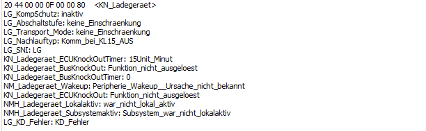
- image.png (11.57 KiB) Viewed 1890 times
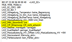
My LAD02 is like this, maybe its about the CP:

- image.png (11.37 KiB) Viewed 1889 times
Do you have any idea what the self test numbers mean? I got a test failed:
Re: MLBevo Charger- 11kw & 22kw Info
Posted: Tue Feb 10, 2026 7:53 pm
by Mitchy
With the port disconnected from the charger unit, I have the following:
PP-PE Resistance @ 2.7kohm
Open Circuit on CP-PE
(I'll measure it with the charger unit connected in a few hours)
I haven't been able to find anything about the tests, however I have several that are failed. I believe #38.
I've seen more/less trigger pending the valid CAN messages, so some are likely due to the time signal, etc. It's also likely some are related to the 2nd charge port input and most definitely the missing LIN system.
I've decoded about half of the BAP signals, although none give any additional control over the charger.
The only major win is the fact one of the messages show realtime charge output in Watts.
There are still some messages outstanding but none that raise the 3500w limit I'm experiencing.
I see your log has the charge rate at 5A, can you still go above that?
Re: MLBevo Charger- 11kw & 22kw Info
Posted: Tue Feb 10, 2026 9:35 pm
by modellfan
Thank you first of all? Do connector and charge unit connected you have 2,7k ohms? That is awkward. I thought they have a standard 4,7k ohms resistor in VW charge ports . I think it is also in the wiki . Might this be the reason for your limiting? PE CP I should measure .
Can I see your code ? Is it directly branches of mine ? I remember me fixing something in the target current calculation. Maybe this is also the reason for your limit.
I only have a 3,5kw outlet at home . Need to go to a friend to measure more . Will do it soon.
In headless action to debug the charger , is first run it without charge port connection and than also without can connection. Maybe this is how I got the Component Protection stuff going on.
Re: MLBevo Charger- 11kw & 22kw Info
Posted: Fri Feb 20, 2026 4:38 pm
by modellfan
Measurements:
With Charger:
PE-CP open
PE-PP 3,19kohm
No Charger:
PE-CP open
PE-PP 4,7kohm
Component Protection is gone, without doing anything then charging. I added some more values to my OpenInverter Parameter overview. I get more and more the feeling, that the wrong plug detection is because of wrong plug lock (not locked, locked statements at the same time). Need to check it with vcds tomorrow. Then I will also activate all temeprature sensors. For now, I just get 2500 W max. Which also might be my charging brick. For now locking it with code is also not working. Might be also that I coded it out.
Re: MLBevo Charger- 11kw & 22kw Info
Posted: Wed Mar 25, 2026 9:19 am
by modellfan
I am wondering is there any way to get the charged AC Energy ? I want to make a total energy consumed counter. Currently I am integrating (idc x udc) + Power loss
Re: MLBevo Charger- 11kw & 22kw Info
Posted: Thu Mar 26, 2026 12:48 am
by Mitchy
I'll try to sort out some of the BAP messages, it may be of some use to you. the Accumulated power may be difficult, but there is likely more to decipher.
I've sorted most of the messages out... But haven't had the chance to document as well as I'd like.
Ironically as soon as I did, I found several others on GitHub that have sorted out messages for the earlier chargers.
https://github.com/norly/revag-bap is a good start to get some base BAP message structure info.
However the most comprehensive gathering of message data is here (and within the root):
https://github.com/karlsen-technologies ... ROTOCOL.md
The newer chargers have slightly different message structure; but the first few messages are similar.
Code: Select all
ASG (0x17332501) ────> FSG (Battery Control Unit)
                 <──── FSG (0x17332510)
You likely will find messages on FunctionIDs:
0x2E contains the output wattage and wattage limits.
Code: Select all
0x0D - Resets the charger
0x0E - << Unknown >>
0x10 - BatteryControlPlug
0x11 - BatteryControlChargeState
0x12 - BatteryControlClimateState
0x1B - BatteryControlPastErrorReason
0x1C - BatteryControlPlugDisplayState
0x26 - BatteryControlChargeModeSelection
0x27 - BatteryControlProfileExtended	(Array)
0x28 - BatteryControlTimerExtended		(Array)
0x29 - BatteryControlChargeTargetTime
0x2A - BatteryControlProfileState
0x2B	- BatteryControlImmediately2
0x2D	- BatteryControlChargingSockets
0x2E - BatteryControlChargeState2
0x2F - BatteryControlHighLevelCommunication
0x30 - BatteryControlContractList
0x31 - BatteryControlAutoUnlock
0x34 - BatteryControlChargeRate
0x35 - << Unknown >>
0x10, 0x11, 0x12 should be similar to the github descriptions.
0x1C - BatteryControlPlugDisplayState
Code: Select all
Consists of two nibbles:
Nibble 0 - State
Nibble 1 - Color
Enum Values:
0	State Off
1	State On
2	State Blink
3	State Pulse
4	State Flash

0	Color None
1	Color Green
2	Color Yellow
3	Color Red
4	Color White
5	Color Blue
0x26 - BatteryControlChargeModeSelection
Code: Select all
Normally in the format 0X 00
Nibble consisting of selecting charge mode timers
0	Timer
1	Immediately
2	Conservation
3	Energy Cost Optimized
4	Energy Mix Optimized
5	Location Based
0x29 - BatteryControlChargeTargetTime
Code: Select all
Likely a time message, but it seems to start at 00 and just start counting as a duration counter.
Byte 0 	Year + 2000
Byte 1	Month
Byte 2	Day
Byte 3	Hour
Byte 4	Minute
Byte 5	Offset?
0x2A - BatteryControlProfileState
Code: Select all
Normally in the format 0X 00 00
Can be changed to correspond to the number of timers configured
Other bytes should relate to Smart Charge State, and Private Current mode?
0	Smart Charging State - Unknown
1	Smart Charging State - Not Available
2	Smart Charging State - Available
3	Smart Charging State - Error
15	Smart Charging State - Init

0	Private Current - Optimization Not Available
1	Private Current - Optimization Available
2	Private Current - Error
15	Private Current - Init
0x2B - BatteryControlImmediately2
Code: Select all
Controls some base charging
You can terminate the charge from this message, but it'll re-enable itself unless you remove the charge request signal
Consists of the LSB nibble
Bit#
4 	Control
3	Activation
2 	Climating
1 	Charging

If you send bit 1 and 4 (such as 0F or 09) it'll stop the charge cycle.
0x2D - BatteryControlChargingSockets
Code: Select all
Consists of enum nibbles:
Nibble 0	Plug Connection State
Nibble 1	Plug Lock State
Nibble 2	Flap Open State
Nibble 3	Flap Closed State
Nibble 4	Error State
Nibble 5	Plug Overruled

0	No Plug
1	Plug A
2	Plug B
3	Plug A & B
15	Init

0	No Flap
1	Flap A
2	Flap B
3	Flap A & B
15	Init

0	No Error
1	Inlet A
2	Inlet B
3	Inlet A & B
15	Init
0x2E - BatteryControlChargeState2
Code: Select all
B0–B1   technicalChargeLevel      u16 LE   (often treated as % * 100)
B2–B3   maxPowerInfrastructure     u16 LE   (hypothesis)
B4–B5   climatisationPower         u16 LE   (hypothesis)
B6–B7   chargeVoltage              u16 LE   (confirmed; e.g. FC 02 = 764 V)
B8      packed nibbles:
          - high nibble: mode
          - low  nibble: chargingPowerReduction
B9–B10  chargingPower              u16 LE   (hypothesis)
B11     chargingHints / flags       u8      (hypothesis; e.g. 0x01 seen as “restricted”)

mode (high nibble of B8): 1=Profile, 2=Holiday, 15=Init
chargingPowerReduction (low nibble of B8): 0=None, 1=Vehicle, 2=Infrastructure
0x31 - BatteryControlAutoUnlock
Code: Select all
Allows you to define if the plug unlocks after a charge cycle or not.
defined for AC and DC charging
defined for one time, or permanent (Exclusive OR)
Again based on a LSB nibble:
Bit:
4	ACChargePermanent
3	DCChargePermanent
2	ACChargeOnce
1	DCChargeOnce

Since there is a rule on not allowing selection of permanent and once together; setting either of the values together, the charger will ignore one of the settings.
0x34 - BatteryControlChargeRate
Code: Select all
This seems most promising, but I think we'll need to send a set kw/km value in order for the calculation to work out.
I only see a change in byte 1, from 0 (~300w) to 1 (~1500w) to 2 (~3500w)

Byte 0 & 1 	Actual Charge Rate
Byte 2 & 3		Average Charge Rate
Byte 4		Charge Rate Calculation
Byte 5		Charge Rate Unit
Byte 6		Average Energy Consumption
Byte 7		Average Energy Consumption Unit

0	km/min
1	km/hour
2	miles/min
3	miles/hour

0	Trip
1	Since Reset
2	Since Last Charge
Re: MLBevo Charger- 11kw & 22kw Info
Posted: Thu Mar 26, 2026 12:58 am
by Mitchy
I've ordered another charger.
Figured I'd either prove two units are non-functional, or migrate over and test some theories in getting a charger to work as a slave unit.
This will require Focci or a CP-PP master; but would allow you to gang chargers together for 11, 22, 33 kw... etc.
Will also reduce the canbus message requirement, as the 2nd charger only needs a partial number of Can messages; and acts like 3 separate current sources.
I've tested your codebase, along with my original teensy code; and the 3500w limit remains.
I did clear the adaptions within ODIS back when bench testing, so I'm wondering if that may have wiped out some base config.
If I do get the 2nd charger and it's fully functional, I'll be willing to try some more risky stuff with the 3500w unit.
I can source an adaption file online and load it for a test.
If all this fails, I'll hop onto the MG bandwagon. I'm UK bound for a week in April, so I'll try my best to source a unit while over there.
Re: MLBevo Charger- 11kw & 22kw Info
Posted: Thu Apr 02, 2026 9:48 pm
by Mitchy
Some positive news!
With a 'New' charger, using my existing codebase, I've been able to achieve ~40A from the EVSE.
The new wattage limit is 8900w (40A @ ~240vAC)
Component protection is showing normal (not triggered... Yet anyway...)
Details of the new charger are:
HW: H35
SW: 0088
ODX: 4007
Part#: 5QE915684CM
Re: MLBevo Charger- 11kw & 22kw Info
Posted: Sat Apr 25, 2026 7:32 pm
by modellfan
The wrongly detected charge plug solved itself away without doing anything. This limiting me to 3,6kw stay:

- image.png (2.12 KiB) Viewed 95 times
I get very weird temperature reading:
Any ideas?
