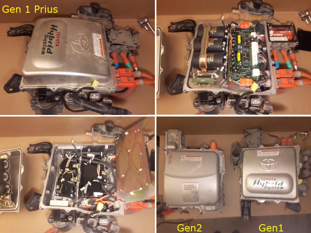
Alexstarex wrote: ↑Sat Jan 25, 2020 10:45 pmin the picture is 1st generation. Need an inverter 2 generation
Hmm. It matches my picture of a Gen 2, not a Gen 1. But I'm far from knowledgeable about all models sold and what years:
Re: Toyota Prius Gen 2 Inverter Controller
Posted: Sun Jan 26, 2020 11:06 am
by konstantin8818
Design of prius Gen3 board as well as Main board V3 utilises STM32F103RBT6 chip, vhich uses P$54(PD2) pin as out for resolver exciter.
And then signal from resolver goes in thrue pins P$22(PA6) and P$23(PA7).
Bluepill equipped with STM32F103C8T6 chip that has got no P$54(PD2).
Is it possible to utilise any of its free pins as exc_out, or I need separate board, like a crop out of gen 3 one, to simulate signal for resolver?
Or maybe Main Board V3 capable of handle prius inverter? I'm not an electronics engineer or hobbyist, I'm mechanics engineer and building my DIY electric car from scratch and looking for a cheapiest way possible=)
I believe software for gen2 also need to be changed for resolver input?
Re: Toyota Prius Gen 2 Inverter Controller
Posted: Sun Jan 26, 2020 12:35 pm
by johu
The V3 main board is so generic that it supports any inverter
Seriously, all you need to do is make a little adapter board that passes the 3 high-side PWM signals through a ULN2003 or discrete transistors. If you so wish you can also level shift the current sensor signals to 0-3.3V and pass the remaining IO signals to a meaningful outside-world connector. Actually an adapter board is on my todo list.
The firmware also detects when it's running on a Blue Pill and re-assigns the pins like so: viewtopic.php?f=3&t=220&start=20#p2623
But given the cheap assembly option I don't think there is much future need for the Blue Pill.
Concerning the boot loader here is what happens:
stm32_loader.hex is the first thing to be executed upon reset/power-up
It listens for an update command for about 100ms, then jumps to the actual firmware
The actual firmware is in stm32_sine/foc.hex and is placed later in the flash
So obviously if the loader isn't flash the MCU will detect an invalid instruction and fault out.
Re: Toyota Prius Gen 2 Inverter Controller
Posted: Sun Jan 26, 2020 12:53 pm
by konstantin8818
Much appreciated!
Re: Toyota Prius Gen 2 Inverter Controller
Posted: Thu Jan 30, 2020 11:00 am
by Jay
Hello all, new to forum....First may I say very great thanks for all the fantastic work done here, especially by Damien.
I've a Gen 1 Prius which I've always wanted to convert to all ev and now with this Gen 2 controller board and Damien's (& Prof. JDK's) Youtube vids I'm hoping it may be doable (although I've just read somewhere that magnets in Gen 1 are wired different so not sure what that means yet?).
Came across some of the descriptions for signals on inverter connector and added missing ones to it's Wiki last night...thought it'd be useful to post a link here to the info I found 'cause it detailed pins on all connectors of hybrid control ecu (think that's the one) and had some useful diagnostic info too. Thanks to Hobbit for this.
I have a Blue Pill set up on breadboard as a minimum system. First of all I had it communicating via USB-TTL to a terminal, but I couldn't get the PWM active. Looking for the various pin statuses was tedious via the terminal, so I set up a D1 mini and added a wireless adaptor to my PC.
For the last couple of days I've been chasing errors on mprot & emcystop. No matter what state I tied PB12 to, the web interface seemed to indicate a floating input. After scratching my head for a while, I went to the source code and found the pin definitions.
This doesn't match up with Damien's schematic; Both mprot_in and emcystop_in are mapped to PB1 in the definitions, whilst Damien has the MG2 inverter fault line routed to PB12.
Tying PB1 to 3V3 got rid of the errors, which ties up with the definitions, but Damien has PB1 as the uaux (12v supply monitor).
With PB12 now unconnected, I was getting ocur errors, which is confusing since ocur_in is mapped to a non existent port on a Blue Pill. I've yet to delve far enough into the code to find out what bk_in is!
Re: Toyota Prius Gen 2 Inverter Controller
Posted: Sun Mar 01, 2020 12:55 pm
by konstantin8818
Now it's time to choose, or just order both Damien's and Johannes's boards.
Re: Toyota Prius Gen 2 Inverter Controller
Posted: Sun Mar 01, 2020 1:15 pm
by Jack Bauer
Can never have too many boards:)
Re: Toyota Prius Gen 2 Inverter Controller
Posted: Wed Mar 04, 2020 5:02 pm
by konstantin8818
Jack Bauer wrote: ↑Sun Mar 01, 2020 1:15 pm
Can never have too many boards:)
Ordered both. Now local shops don't know what components I need I talk about components, listed in PriusG2_V1_BOM.ods
They say they don't know what are those strange writings in English
There are no BTS117BKSA1, TR10S05 and MCP2562-E/P components awailable for a retail purchase in my country Damien, can you please include those for an additional price?
Re: Toyota Prius Gen 2 Inverter Controller
Posted: Thu Mar 05, 2020 3:24 am
by MattsAwesomeStuff
I found everything I needed from Digikey. But I presume any of the bit component sellers would have everything.
Re: Toyota Prius Gen 2 Inverter Controller
Posted: Thu Mar 05, 2020 5:56 am
by konstantin8818
MattsAwesomeStuff wrote: ↑Thu Mar 05, 2020 3:24 am
I found everything I needed from Digikey. But I presume any of the bit component sellers would have everything.
No shipment to Belarus from digikey. Farnell's official distributor in Belarus no longer exist.
If you imagine Russia and Europe as two towns, Belarus will be road between them. Roads have no postal codes and no one cares. Belarus is like a black hole - to import something from Europe, you need to pay toll, Russian shops(not all, but many) on the other hand don't offer shipment to Belarus.
There are shops in here that got all that stuff, but they only work with companies and businesses.
I hope you got the overall picture
Re: Toyota Prius Gen 2 Inverter Controller
Posted: Sun Mar 08, 2020 10:30 am
by SciroccoEV
Bye bye Blue Pill.
No way to start PWM without tripping the overcurrent/brk-in on either of my two examples.
SciroccoEV wrote: ↑Sun Mar 08, 2020 10:30 am
Bye bye Blue Pill.
No way to start PWM without tripping the overcurrent/brk-in on either of my two examples.
It looks like a workaround was found, but it definitely doesn't work on either of my boards. I had the other boards right from the start, but used the BP because it's easier to fit them on a breadboard.
Re: Toyota Prius Gen 2 Inverter Controller
Posted: Sun Mar 08, 2020 12:55 pm
by MattsAwesomeStuff
I was on an electronics kick for 3 months 'cause the junkyard I bought my Gen 2 inverter from had a 90 day warranty on the inverter. When the 90 days passed I hadn't got it working yet, so it's sat on a shelf for the last couple months and I've gone back to welding and grinding (and welding, and grinding, and welding, and grinding, and the joys of combining 2 50-year old cars together with no experience).
Not sure I understand Scirocco's comment.
The Blue Pill doesn't work when you actually go to power up the inverter, or, just that your particular Blue Pill(s) have a slightly different STM32 chip that's shittin' the bed so you threw in the towel and got a properly sourced STM32 chip?
(I.E. Is this going to be a problem for everyone, some of us, or just you?)
Re: Toyota Prius Gen 2 Inverter Controller
Posted: Mon Mar 09, 2020 9:46 pm
by SciroccoEV
MattsAwesomeStuff wrote: ↑Sun Mar 08, 2020 12:55 pm
Not sure I understand Scirocco's comment.
It seems you didn't read the thread I referenced. I'll paste some relevant bits of it here.
Johu wrote:bk_in is on PB12 and it must be because it's the hardware break input of the timer. It seems there is a problem with it, Damien and me are currently investigating.
Johu wrote:Well, it would seem the Blue Pill has a little layout problem. So no matter if you set the break input active high or low it trips out as soon as the PWM runs, even though the break input is tied to ground or VCC, respectively. If the break function is disabled per timer register, all runs ok.
Now, I disabled the PWM1N output which is adjacent to the break input. Et voila: no trip.
There was a code version associated with the last post, which I assume was one that worked despite the board layout. It didn't work on mine, so I switched to the other board. All the boards are using STM branded uProcessors, but with the CHN marking showing the die was packaged by STATS ChipPAC Shanghai Co. Ltd.
Damien and Johu have effectively abandoned using these cheap development boards now that full SMD assembly is so cost effective direct from JLC-PCB. I still see some merit in using them; Damien's PCB didn't incorporate level shifters for the bipolar current sensor output of the Gen 2 intelligent power module, so |'m testing a circuit out on the breadboard.
The higher pin count board didn't cost that much more, but it has dual row headers, so it can't just be plugged into a breadboard. I now have a 'hairball' of flying leads from the dev board to the breadboard, but I do now have PWM and can do some further testing.
Re: Toyota Prius Gen 2 Inverter Controller
Posted: Tue Mar 10, 2020 6:32 am
by johu
You could try installing a strong pull-up (say, 1k) directly at the STM32 pin for bk_in. Still agree the Blue Pill has many issues. I think the existing hardware out there can be made to work but reading all this I wouldn't base a new design on it.
Re: Toyota Prius Gen 2 Inverter Controller
Posted: Thu Mar 12, 2020 8:10 pm
by SciroccoEV
johu wrote: ↑Tue Mar 10, 2020 6:32 am
You could try installing a strong pull-up (say, 1k) directly at the STM32 pin for bk_in. Still agree the Blue Pill has many issues. I think the existing hardware out there can be made to work but reading all this I wouldn't base a new design on it.
Connecting the pin directly to the power rail didn't make any difference!
Anyway, I have things working with the other board;
Re: Toyota Prius Gen 2 Inverter Controller
Posted: Fri Mar 13, 2020 12:47 am
by MattsAwesomeStuff
SciroccoEV wrote: ↑Mon Mar 09, 2020 9:46 pmIt seems you didn't read the thread I referenced.
I did, but, like most things here, I only understand half of it.
Damien's PCB didn't incorporate level shifters for the bipolar current sensor output of the Gen 2 intelligent power module, so |'m testing a circuit out on the breadboard.
Neat, I'll need to copy that if I end up sticking with my Blue Pill board.
Anyway, I have things working with the other board
Thanks for sharing your progress. It's looking like lots of us are going to be more or less preventatively stuck in our basements and shops, so, hopefully I'll get a lot of work done this spring :p
Re: Toyota Prius Gen 2 Inverter Controller
Posted: Mon Mar 16, 2020 10:49 am
by konstantin8818
I've found all needed components for Damien's board except of one: switching regulator TR10S05 https://www.chipdip.ru/product/tr10s05 ... tor-8-28v This shop in Moscow does not send parcels to Belarus.
I've found this regulator with low voltage drop: LM2940CT-5.0 / NOPB https://www.chipdip.by/product/lm2940ct-5.0-nopb Same shop in Belarus but stock is separated and they have got no TR10S05. This is some kind of circus ...
Is it possible to replace TR10S05 with LM2940CT-5.0 / NOPB. Will it do the trick?
Re: Toyota Prius Gen 2 Inverter Controller
Posted: Mon Mar 16, 2020 10:56 am
by Jack Bauer
I have sent you a built and tested board:)
Re: Toyota Prius Gen 2 Inverter Controller
Posted: Mon Mar 16, 2020 11:54 am
by konstantin8818
Jack Bauer wrote: ↑Mon Mar 16, 2020 10:56 am
I have sent you a built and tested board:)
WHOA! I can't thank you enough! I'll sent a donation as soon as my payday!
Now I need to deal with all those components, coming my way from all over the world Maybe I'll try to recreate your board.
Re: Toyota Prius Gen 2 Inverter Controller
Posted: Tue Mar 24, 2020 9:01 am
by SciroccoEV
I'm now trying to chase down why the current sensor channels on my board appear to have different gains. The two throttle channels behave as expected, but feeding IL1 & IL2 with 0 to 3.3v signals results in values between approx. +/-400 amp on one channel and +/-250 amp on the other.
The zero offset is calibrated every time the inverter is started, but I'm also seeing an offset between the channels when I return to the initial applied voltage.
I can't see any sneak circuits on the board and both inputs have >3Mohm impeadance to the supply rails on the Fluke.
I'll write some quick text code just to check the raw ADC values.
Re: Toyota Prius Gen 2 Inverter Controller
Posted: Wed Mar 25, 2020 3:42 pm
by SciroccoEV
Now just what could be causing this...
Re: Toyota Prius Gen 2 Inverter Controller
Posted: Thu Apr 09, 2020 9:36 am
by konstantin8818
My board has arrived Thank you, Damien! Now just need to wait when contactors make it to Belarus, as they seems to stuck in Israel for over two weeks already...