Page 6 of 8
Re: [WIP] Voltswagen T2 -76
Posted: Thu Mar 06, 2025 6:24 pm
by Cera
Hmm. Some more Youtube videos later I now know how to use Fusion simulations. That was surprisingly easy and convenient.

With simulation (S235 steel) 3mm L-profile shows to be "fine" but ~1.6 SF
But nevertheless I decided to upgrade to 40x40x4mm L-profile.
Also went with rectangular tube on the front mount instead of the U-profile in previous plans. Simulation shows U-profile (50x30x3mm) similarly "fine" but I found a piece of S355 50x30x4mm tube so.. Whynot.

With these changes the whole construction is solid for 1kN downward force (~100kg for motor) + 280Nm remote moment.
The weakest section left is at the top mount where the rear arm tries to apply torsion forces to it, but in reality the whole structure is solid even without that torsion arm so it's not going to be an issue. Fusion just shows it as yellow when force is applied to all bolt holes. And even still SF 2.25 is enough for that, since all the rest of the structure can withstand the forces without the whole piece.
With 4mm S235 steel the L-profiles are well within SF3+ despite their length too.
Stresses along same spots
And for curiosity checked the construction in reverse too (280Nm to other direction)
And it's perfectly solid.
It's good to know you can push the full 280Nm to tyres in reverse too!

These are also maximum loads and there'll probably be no cases where the structure would see the full 280Nm since that will be limited in VCU
Re: [WIP] Voltswagen T2 -76
Posted: Thu Mar 06, 2025 7:42 pm
by Jacobsmess
Didn't realise fusion could do this. Maybe I'll need to have a look at modelling my designs in it. Which motor mounts are you using? I'm currently looking at my options.
Re: [WIP] Voltswagen T2 -76
Posted: Thu Mar 06, 2025 7:47 pm
by Cera
Jacobsmess wrote: ↑Thu Mar 06, 2025 7:42 pm
Didn't realise fusion could do this. Maybe I'll need to have a look at modelling my designs in it. Which motor mounts are you using? I'm currently looking at my options.
I contemplated pretty much every stock option available but in the end I bought the original 1600cc engine rubber mounts. So I'm hanging the crossmember with these:
https://www.serial-kombi.com/en-GB/bay- ... 1979-n3651
Front mount is connected to the frame using the transmission nose mount:
https://www.serial-kombi.com/en-GB/bay- ... ox-n330152
And the top mount from which it's hung down is the stock transmission/bell housing mount.
This way I can neatly have vibration dampeners on all of the mounting locations without having to modify the chassis/body at all.
Re: [WIP] Voltswagen T2 -76
Posted: Thu Mar 06, 2025 10:12 pm
by jrbe
280nm? Looks like you forgot the gear ratio for the actual calculated torque at the wheels. I think you'll end up around 2800.
Edit, doing the math it's about 2016nm. 254nm at the motor X 7.94 gear ratio for a gen 2 leaf.
Also, when you fix a face it can distort the simulation. Sometimes it's best to make a very simple piece that it's bolting to and put the force on that.
Or even better, draw it up so you can apply the torque to it.
Re: [WIP] Voltswagen T2 -76
Posted: Thu Mar 06, 2025 10:30 pm
by Cera
Correct me if I'm wrong, but doesn't the gearbox gearing reduction affect the forces experienced at the drive shafts but does not change the reaction torque at the motor mounts?
Say 3:1, the drive shafts experience three times the engine torque, but the motor mounts can only ever react to the torque generated by the motor itself (i.e. 280Nm max given for Leaf 110kW) and are oblivious at the torque the wheels experience after the gearing. Therefore, the max. moment reaction at the mounts is directly due to the motors own torque production and does not depend on what's going on "downstream" from that. The gearing only scales the torque applied to the drive shafts and wheels?
Re: [WIP] Voltswagen T2 -76
Posted: Thu Mar 06, 2025 10:41 pm
by jrbe
The torque at the wheels acts through the driveshafts and is opposed by the transmission mounts.
You are thinking of the torque between the motor and transmission.
Re: [WIP] Voltswagen T2 -76
Posted: Thu Mar 06, 2025 10:43 pm
by Cera
Hmm. I need to double check this with fresh brain tomorrow.

It's way too late for physics here.
Re: [WIP] Voltswagen T2 -76
Posted: Fri Mar 07, 2025 12:08 pm
by Cera
jrbe wrote: ↑Thu Mar 06, 2025 10:41 pm
The torque at the wheels acts through the driveshafts and is opposed by the transmission mounts.
You are thinking of the torque between the motor and transmission.
I've spent the whole morning thinking of this and still ain't sure.
In my mind:
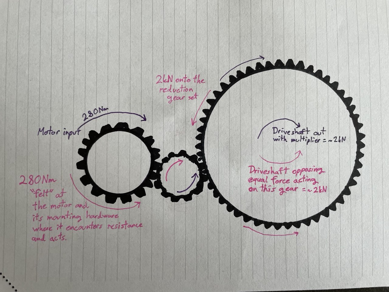
Yes torque (280Nm) is generated by the motor and goes to input gear -> reduction -> out to driveshafts as ~2223Nm.
Examining from other direction (force applied by the driveshaft) the moment is first encountered by the gearbox output gear, which will transmit the force to the next gear, then to input gear, then to motor (which then "feels" the force).
The gearbox gears have bearings and are freely spinning, so any rotational force of the driveshaft should primarely act on the gears, not the transmission case (and therefore not to its mounts) and only transmits the force to the case/mounts where it encounters resistance (such as motor trying to spin "against it").
So 280Nm * 7.94 = 2223Nm from motor to the driveshaft
and if driveshaft then counters that with equal/opposite reaction, 2223Nm / 7.94 = 280Nm gets transmitted to the motor where it is "felt" and said force is transmitted to the case and the mounts.
This of course assumes the gears are free to rotate and transmit the force, but if they aren't there's bigger issues at play already :'D The gear should be able to withstand the full 2223Nm (as they would encounter that on driving on reverse anyway).

Re: [WIP] Voltswagen T2 -76
Posted: Fri Mar 07, 2025 12:22 pm
by tom91
Look at system level. Where does the force come from/gets countered. wheels to the road. so the whole motor+reducer will pivot at 2kNm around the output shafts.
The motor + gears are an enclosed system so torque is contained within, the only external torque path is the shafts.
Re: [WIP] Voltswagen T2 -76
Posted: Fri Mar 07, 2025 5:14 pm
by Cera
Yeah I don't know.
I'm just a lousy paramedic, not a physics person.
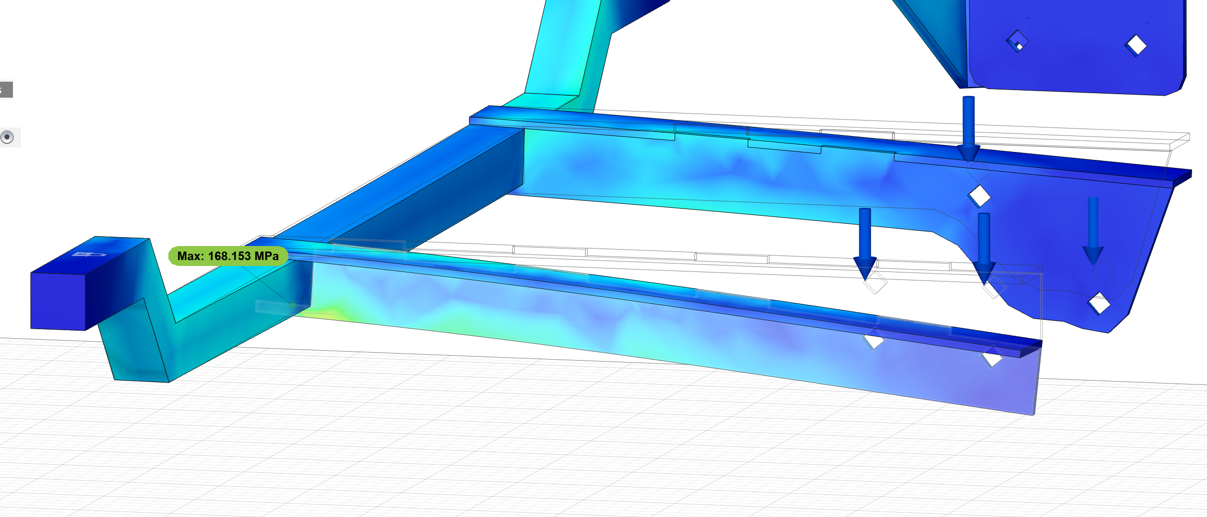
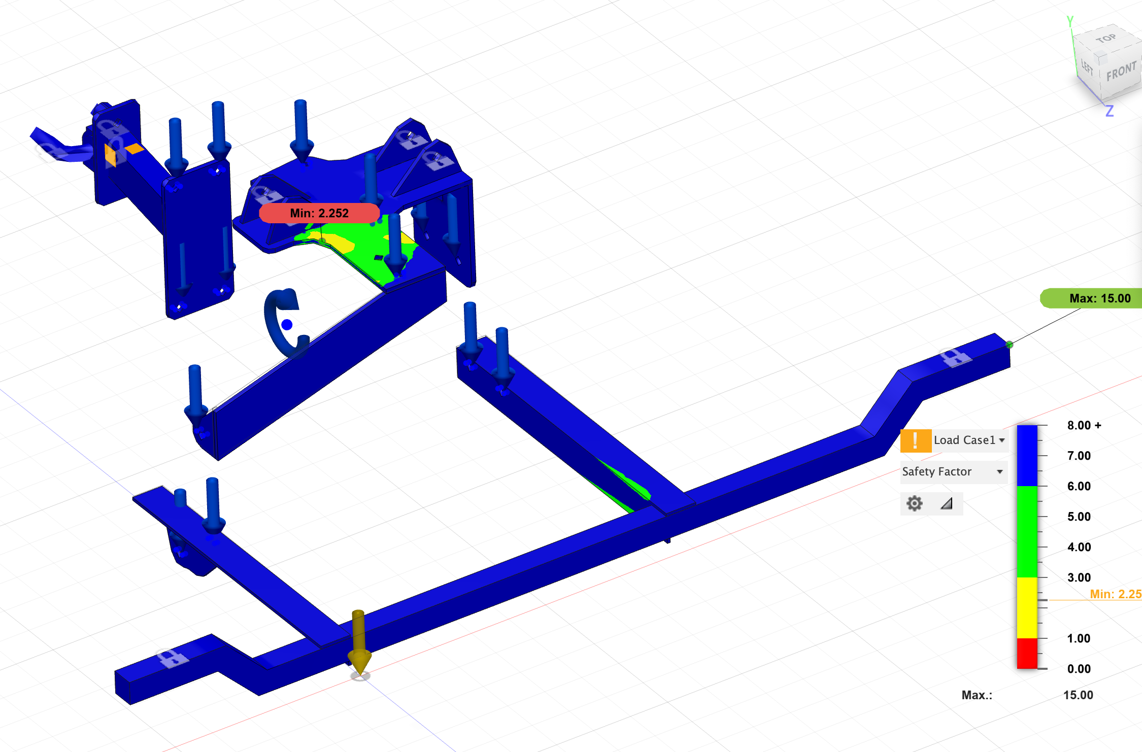
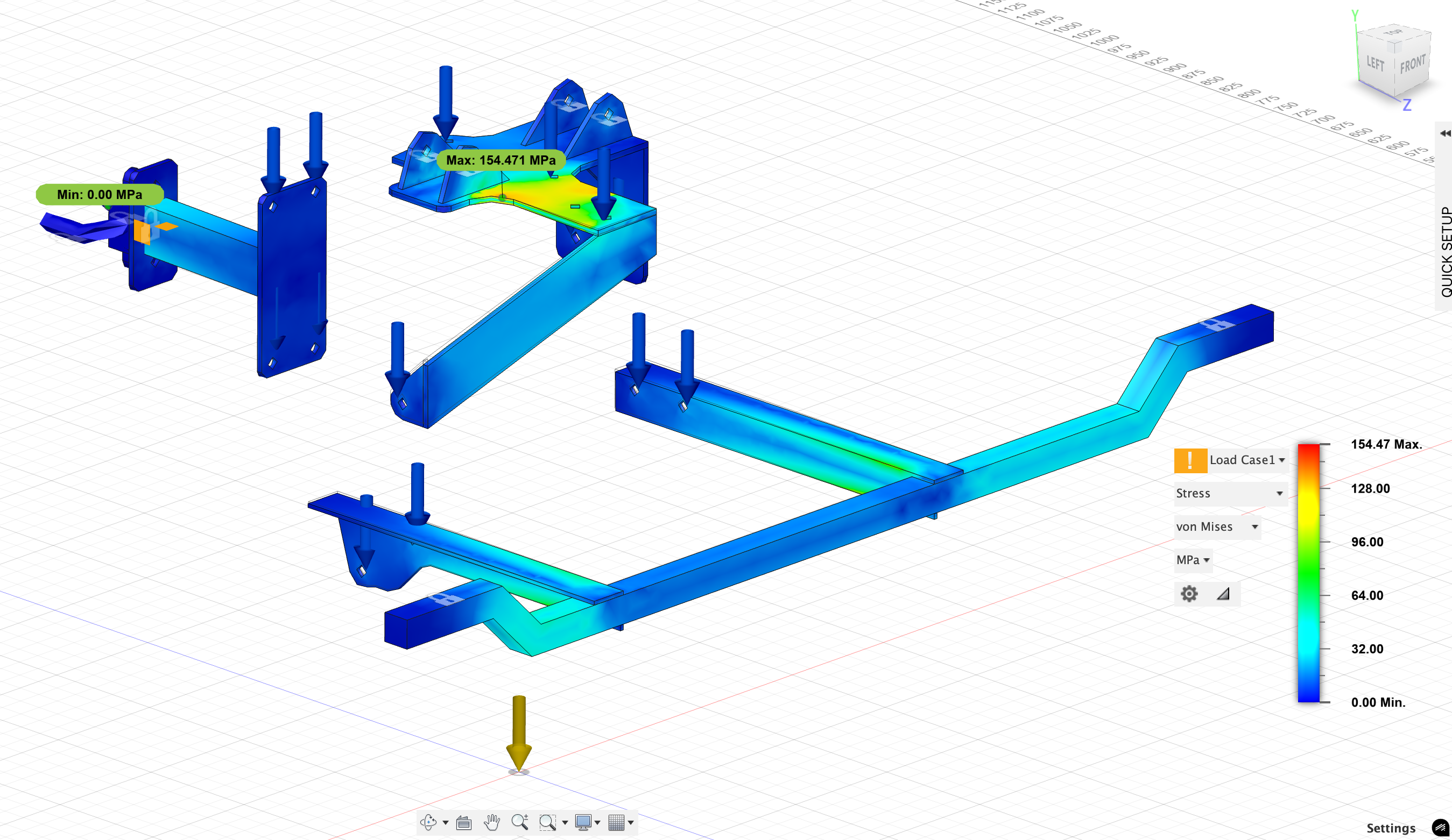
I made is stronger just to be sure. This is stresses with the improved design. 2223Nm torque + 1000N downward force.
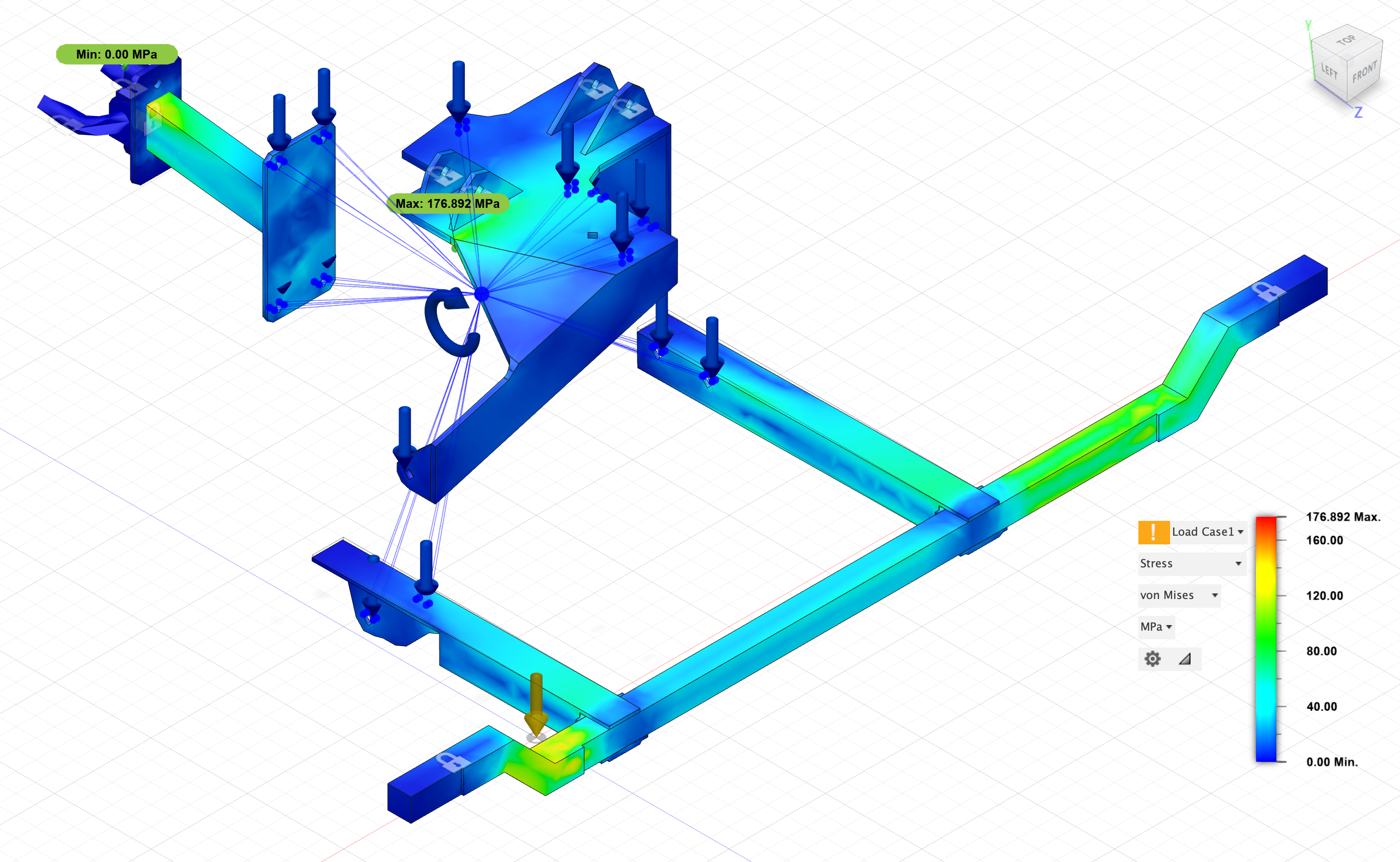
So replaced the L-profiles with rectangular tube (40x40x4) which has a 3mm flat piece between it and the crossmember to allow for more equal distribution of forces.
Added an extra flat onto the top mount to make it more 3-dimensional and supporting the hanging arm wrapping around the motor.
From below:
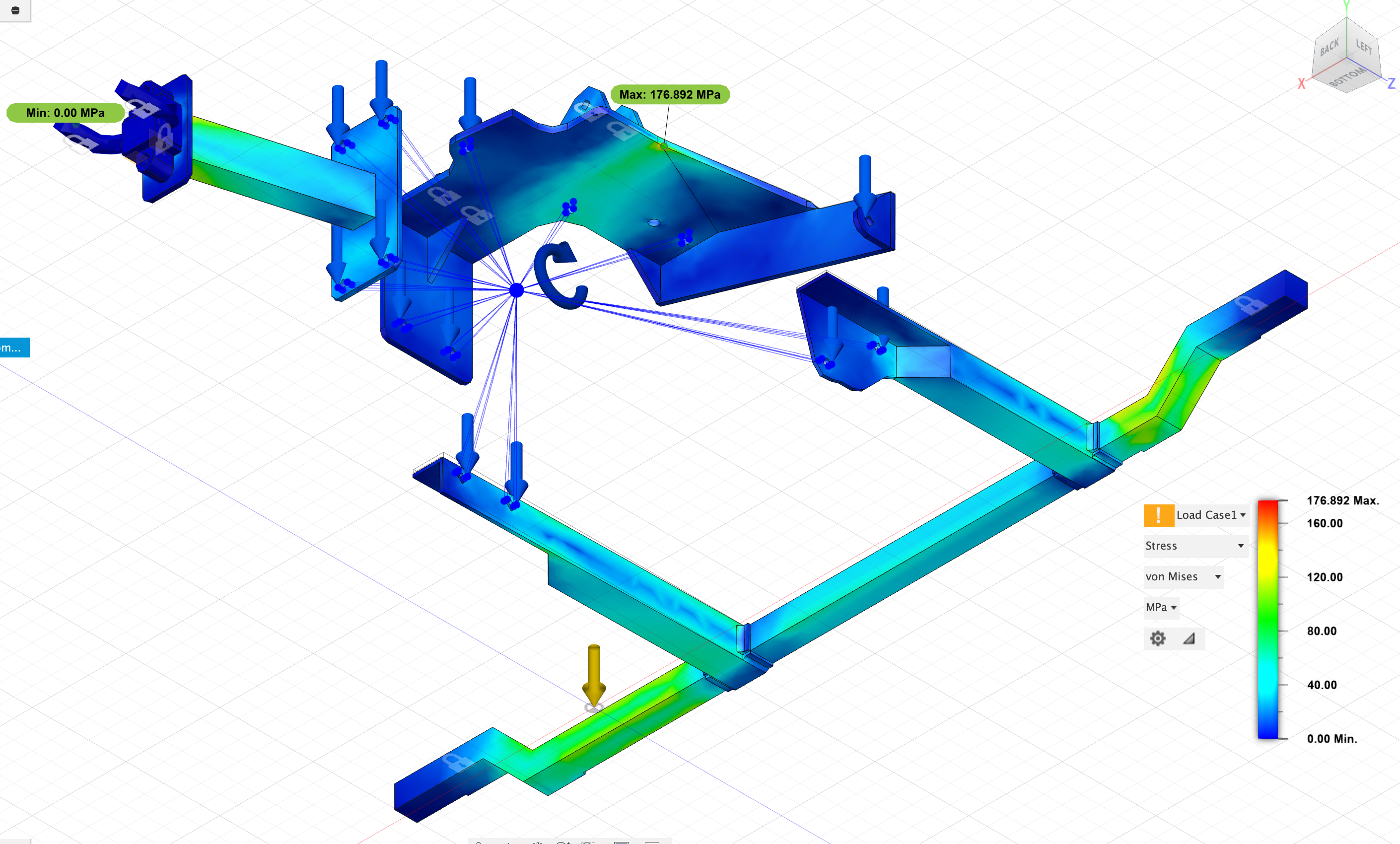
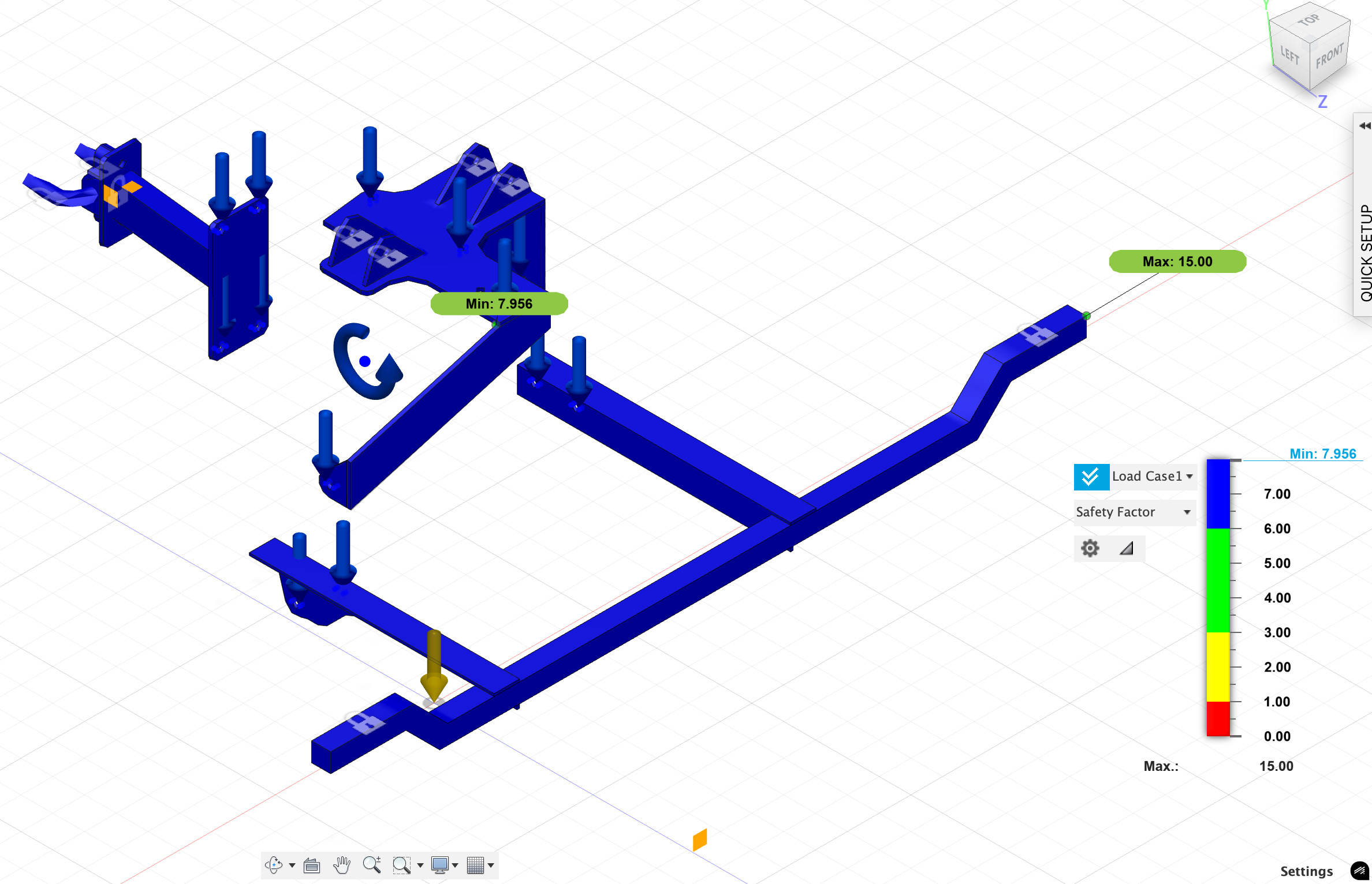
The weak points are now on the crossbeam, and those are around SF2.5 which is not perfect but I've a hunch this will tear the original motor rubber dampeners into pieces before any of this steel breaks anyway.
And again, considering this is theoretical max. forces. Limits to VCU. This is not a race car, but a summer camper and it'll be driven like one.
Idk. I'm fairly happy with this design now, this is why I love posting to forums, get feedback and improve.
Re: [WIP] Voltswagen T2 -76
Posted: Fri Mar 07, 2025 10:25 pm
by jrbe
You can try it as is but the stress analysis looks off to me. Will it do an animation showing the twist / bends?
You might have to extrude little cylinders on the flat pieces and attach to those so it doesn't assume the load is spread over the whole face.
Re: [WIP] Voltswagen T2 -76
Posted: Fri Mar 07, 2025 10:58 pm
by Cera
I think I'm going with it as is (at least well, todays mood, but the steel shop is closed 'till mondays so here's whole weekend to overengineer this still!
).
It does show max. displacement and twist/bend but I've set it to "show actual" instead of exaggarated so it's not that visible in the pictures.
Forces are acting on the bolt hole inner surfaces, so should be fairly good representation - or at least as good as with extruded pegs from those same holes I guess.
This throws it off with the upper mount a little though, since it doesn't understand the underside of it is tightened against the motor and cannot twist like it thinks. Too lazy to correct that since it has little effect to the analysis.
Re: [WIP] Voltswagen T2 -76
Posted: Tue Mar 11, 2025 10:28 am
by Cera
Battery box, 5th iteration:
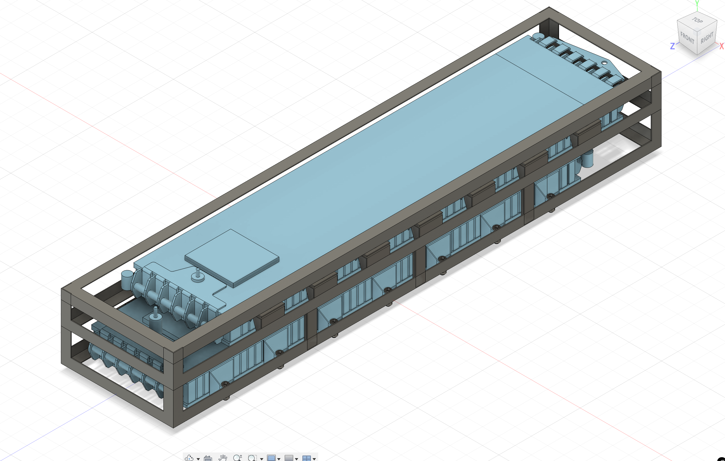
These Tesla M3 modules are pain to work with but I think I've finally come up with a design which allows mounting them from their original mounting points (the only load bearing structure on them are the sides as far as I'm aware?).
Goals for the design:
- Fits 2x modules on top of each others into max. 1500mm space.
- Enough space to safely run wiring & coolant hoses
- Possible to weld out of what's readily available off the shelf, without any custom metal profiles requiring special bending tools
- Relatively cheap & lightweight
Dimensions for this 1500mm x 345mm x 200mm
Almost entirely 30x30x2mm L-profile
A few 20x20x2mm (and 25x25x2mm) L-profile bits for the mounting hardware.
Some flat 2mm steel for reinforcements / gussets. I plan on plasmacutting them to shape, then welding.
M8 bolts for holding the modules
M12 bolts for fixing the box to the vehicle
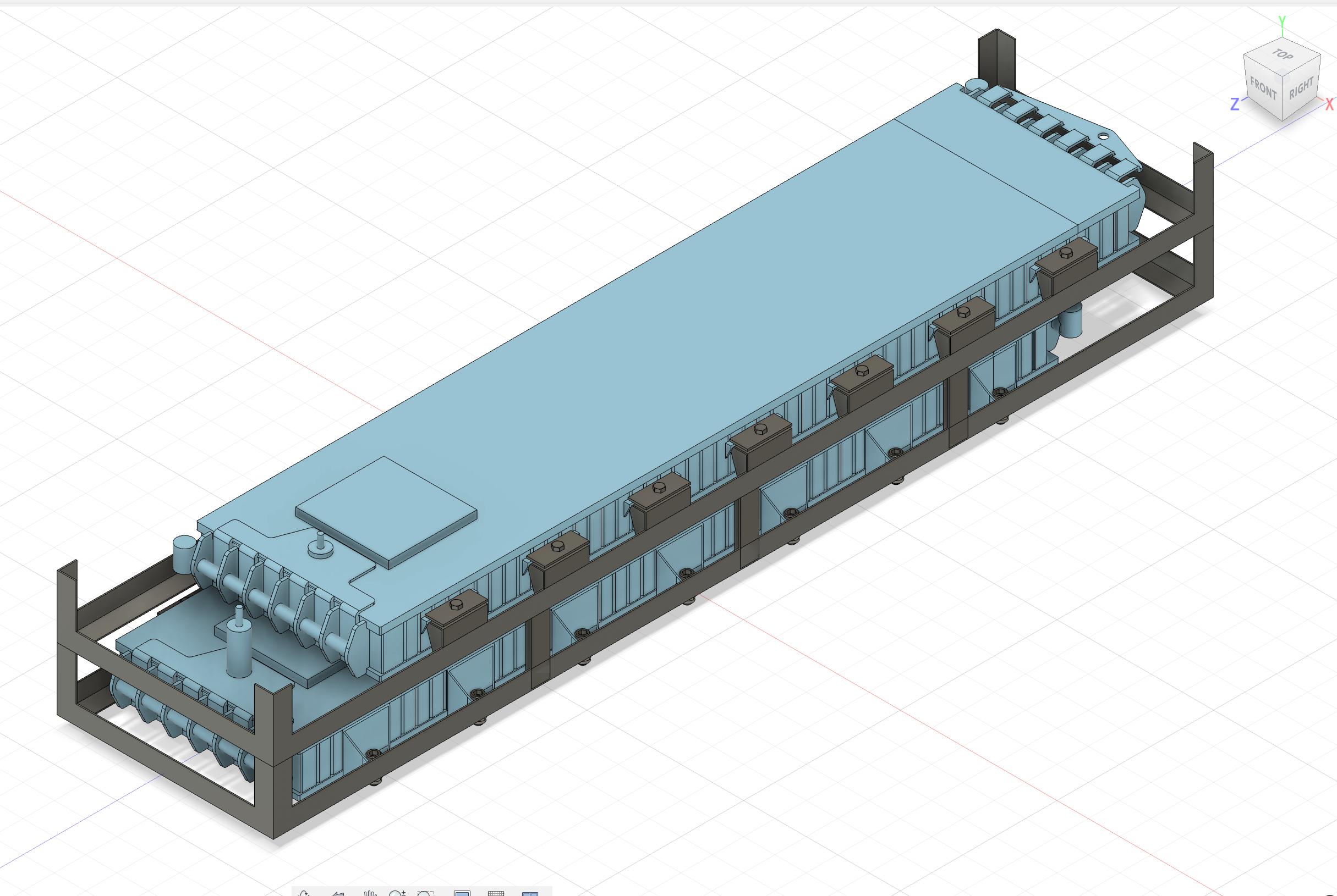
Welding all the mounting points to correct locations will probably be hell but we'll see

I might add some reinforcement braces for peace of mind (and crash situation) but for this design Fusion shows it safe (with minimum safety factor of 15) for 1kN force from above, as in all the weight on the normal mounting points.
I ran simulations upside down too, comes up with min. SF7.1, but it's of course not fully descriptive for rollover since it lacks impact forces etc.
Should be possible to wiggle the lower module in first, but if not, then assembling it with bolts and nuts around the modules
Finally lining the inside with suitable insulating material just for being on the safe side and covering the walls. These are mounted into the cargo space of the vehicle, so they're not out at the mercy of the elements.
Either two cases right next to each others (2+2) or one case below the rear bench and other behind the front seats as planned before.
Re: [WIP] Voltswagen T2 -76
Posted: Tue Mar 11, 2025 10:48 am
by nkiernan
I battled with a range of module mounting options for these too. Some detail on ideas I had to try reduce parts and complexity:
viewtopic.php?p=35408#p35408
Re: [WIP] Voltswagen T2 -76
Posted: Tue Mar 11, 2025 10:53 am
by nkiernan
If you have the Model 3 battery modules already, make sure to regularly check cell tap voltages...seeing cases where randomly cell blocks can start dropping voltage, and I have a case where I didn't notice in time and now one module is scrap! This was while they were in storage during the build
Re: [WIP] Voltswagen T2 -76
Posted: Tue Mar 11, 2025 11:01 am
by Cera
nkiernan wrote: ↑Tue Mar 11, 2025 10:48 am
I battled with a range of module mounting options for these too. Some detail on ideas I had to try reduce parts and complexity:
viewtopic.php?p=35408#p35408
That's a wildly different approach to the same problem, heh.

I do like it! You don't happen to have dimensions for these? What plastic you used? I might have to weigh my options.
nkiernan wrote: ↑Tue Mar 11, 2025 10:53 am
If you have the Model 3 battery modules already, make sure to regularly check cell tap voltages...seeing cases where randomly cell blocks can start dropping voltage, and I have a case where I didn't notice in time and now one module is scrap! This was while they were in storage during the build
I do have them, but they've been sitting in a container. I've not really had anywhere to put them since I don't want to just lay them onto the floor (as the bottom is fragile) so I've kind of just left them in their box for now and I'm hoping for the best. Maybe I've been overly cautious? I see you've tested them just on a table..
I'm kind of scared about the HV side still and have to get proper safety gloves and things set before I start poking at them for more.
I should have all the original BMS, M3 charger, wiring, etc too, but haven't really decided what to use. Learning from the scratch it's kind of slow progress.
Re: [WIP] Voltswagen T2 -76
Posted: Tue Mar 11, 2025 11:23 am
by nkiernan
I modelled these in Solidworks and have all the DXF's I can share if useful. I had them profiled from a cheaper plastic so the cut edges weren't great and I had to do some filing at corners. I'd go a more rigid PTFE or similar to get a good cut edge as the parts slot together to form the assembly. Idea is to stack all forces through the plastic outer casing of the modules, space them off the bottom of the battery box, reuse the original TM3 pressure valves and coolant connectors. The three straps around the battery box coincide with the additional profiled plastic ribs, so when closed and fit to car, its pretty solidly held. The plastic frame is a snug fit inside the battery box to prevent movement.
You can use an Arduino and connect to the main LV connector to read out all the cell voltages and temperatures. Would advise periodically checking the voltages for all 96 cells.
https://openinverter.org/wiki/Tesla_Model_3_Battery
Re: [WIP] Voltswagen T2 -76
Posted: Tue Mar 11, 2025 11:43 am
by Cera
nkiernan wrote: ↑Tue Mar 11, 2025 11:23 am
I modelled these in Solidworks and have all the DXF's I can share if useful. I had them profiled from a cheaper plastic so the cut edges weren't great and I had to do some filing at corners. I'd go a more rigid PTFE or similar to get a good cut edge as the parts slot together to form the assembly. Idea is to stack all forces through the plastic outer casing of the modules, space them off the bottom of the battery box, reuse the original TM3 pressure valves and coolant connectors. The three straps around the battery box coincide with the additional profiled plastic ribs, so when closed and fit to car, its pretty solidly held. The plastic frame is a snug fit inside the battery box to prevent movement.
Would be useful since I've yet to decide what route to take and I admit I do like the idea of these plastic inserts more than my L-profile cage idea. But it depends on what materials I can get and work on too, etc. Our makerspace's laser cutter doesn't like ABS/PTFE due to toxic fumes if I remember correctly. But more options = better.
Yeah I really should

It's been a lot and I kind of decided to focus on the motor mounting first, then open up the battery pack and peek inside carefully.
But yeah like said I don't even have the PPE yet for HV things, and plenty to read ahead of me before jumping into poking wires at those things...
But first, should figure out how to rest them somewhere accessible. Maybe cutting out some plastic frame out of acrylic to support the edges from below, like in your mounts. I'm unsure if acrylic is suitable for doing permanent mounts, but would work temporarily at least.
Re: [WIP] Voltswagen T2 -76
Posted: Fri Apr 04, 2025 9:44 pm
by Cera
Rights, enough practice and time to tackle the proper pieces!
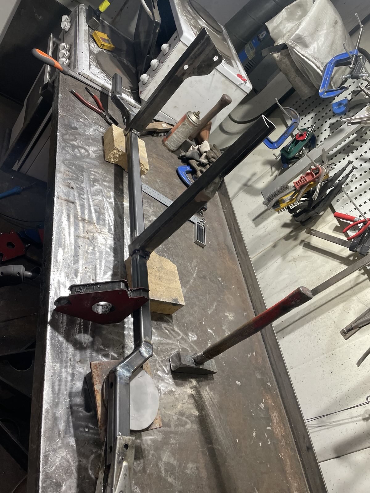
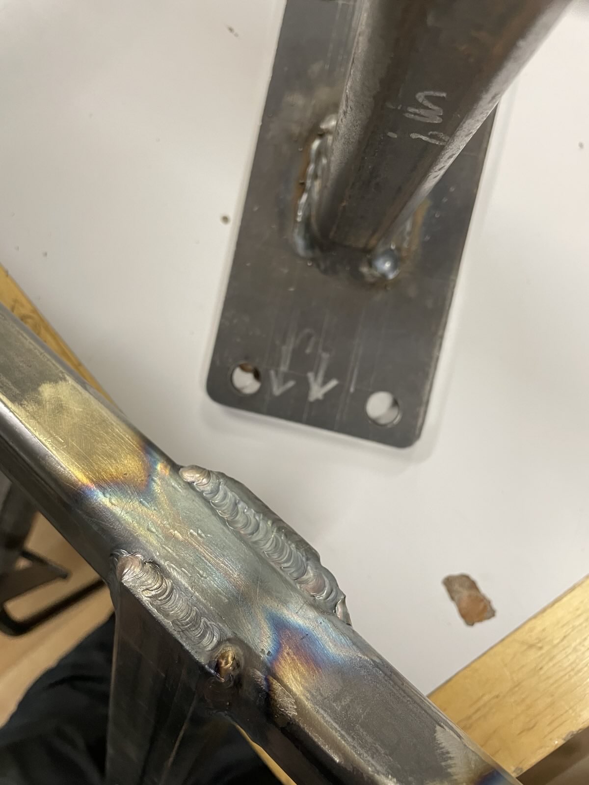
In the end I ended up quite liking TIG welding.
Much more than our MIG which spews fire and destruction and feels like hard to control. TIG was like zen meditation in comparison, slow and peaceful.
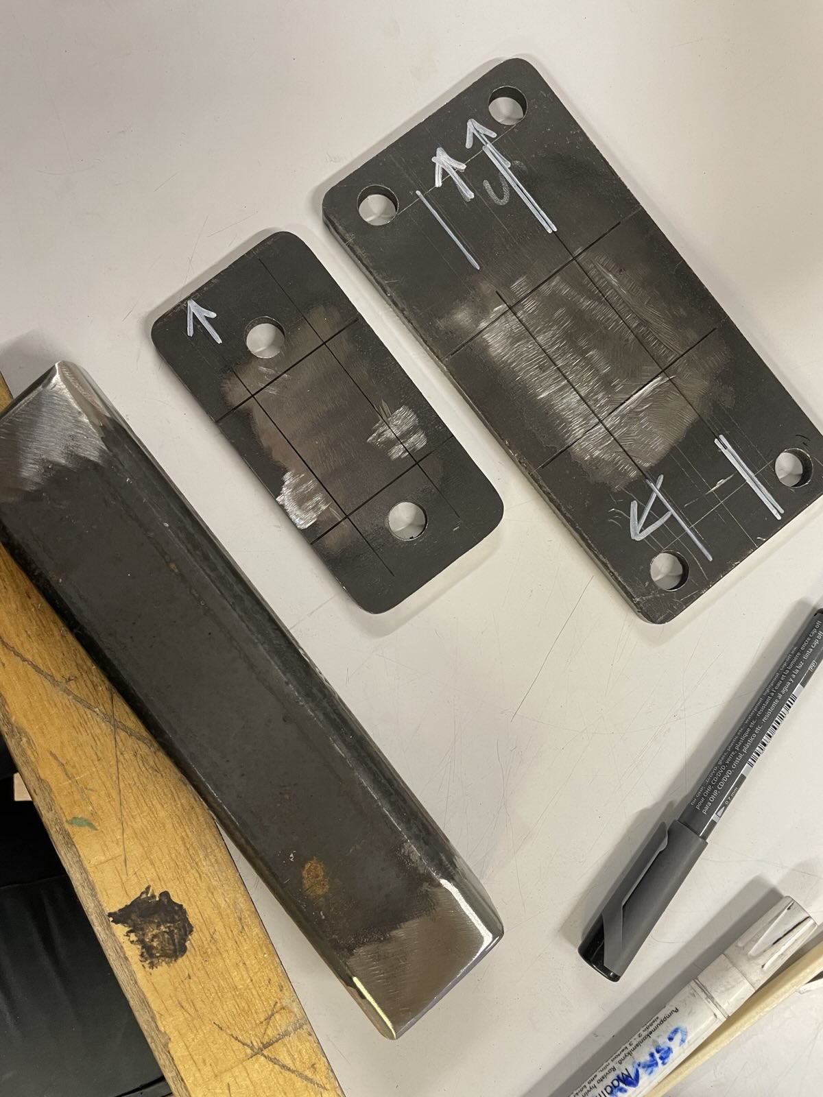
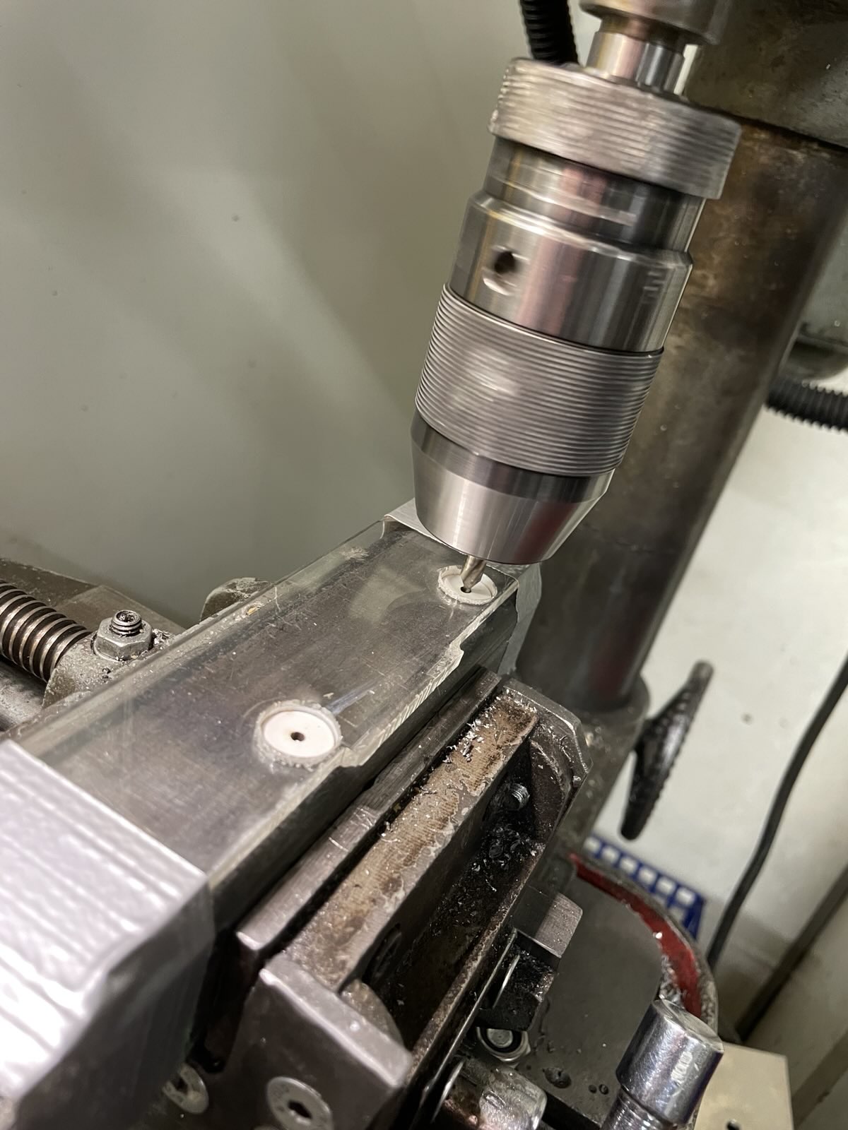
Drilling some holes. I used the lasercut test pieces to locate the bolt holes and pilot drilled to exact spot.
And with that done
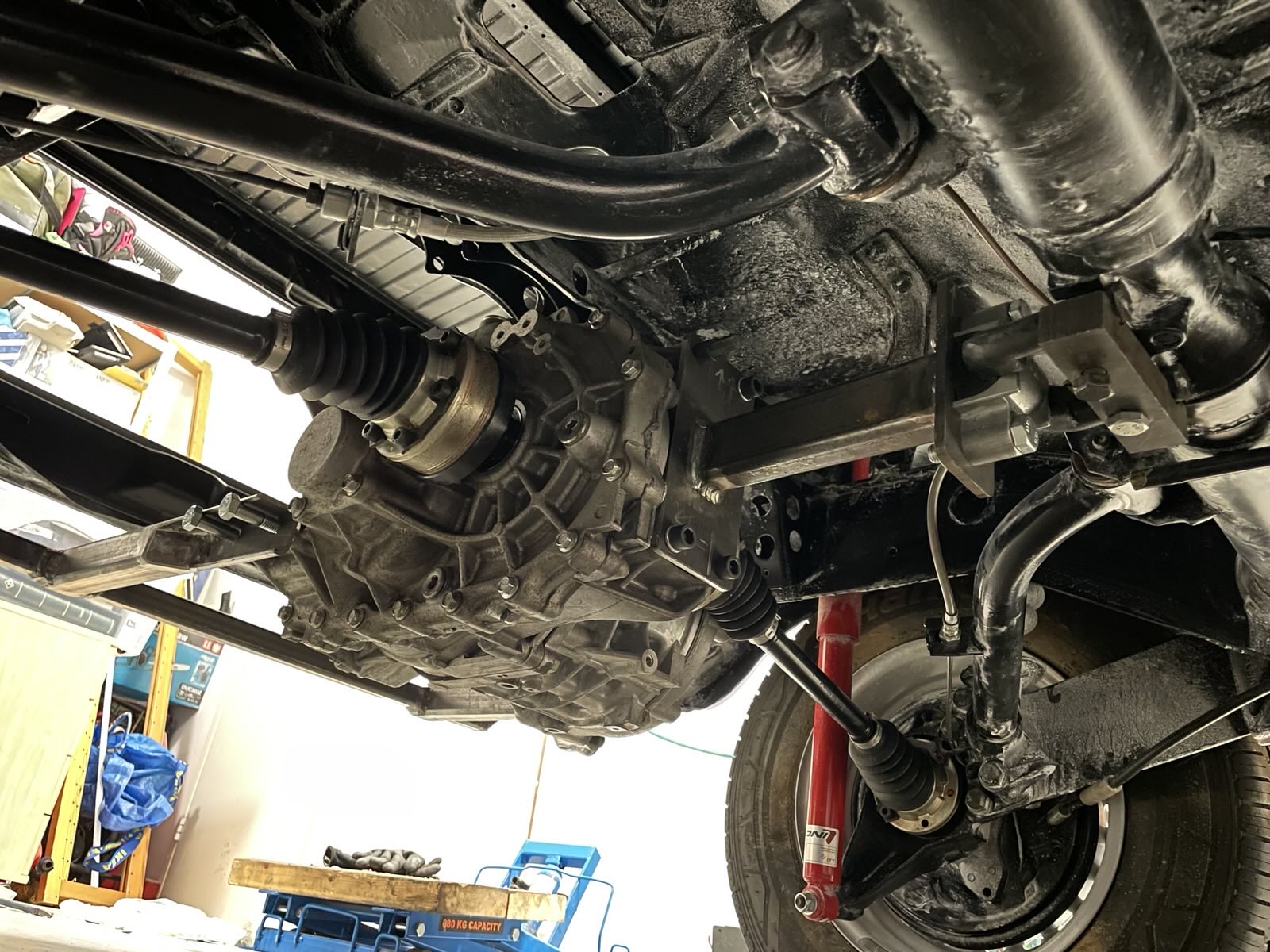
Motor is IN
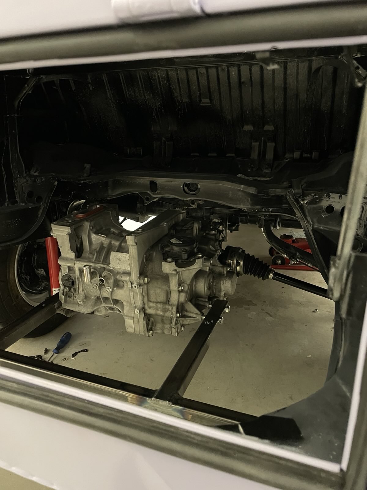
Like the test pieces, the real steel mounts fit perfectly. Or they would, if I wouldn't have made one measuring mistake and now the gap for the motor is 1cm too wide. I'm just going to weld in some spacers to fix that, fortunately not a bigger mistake.
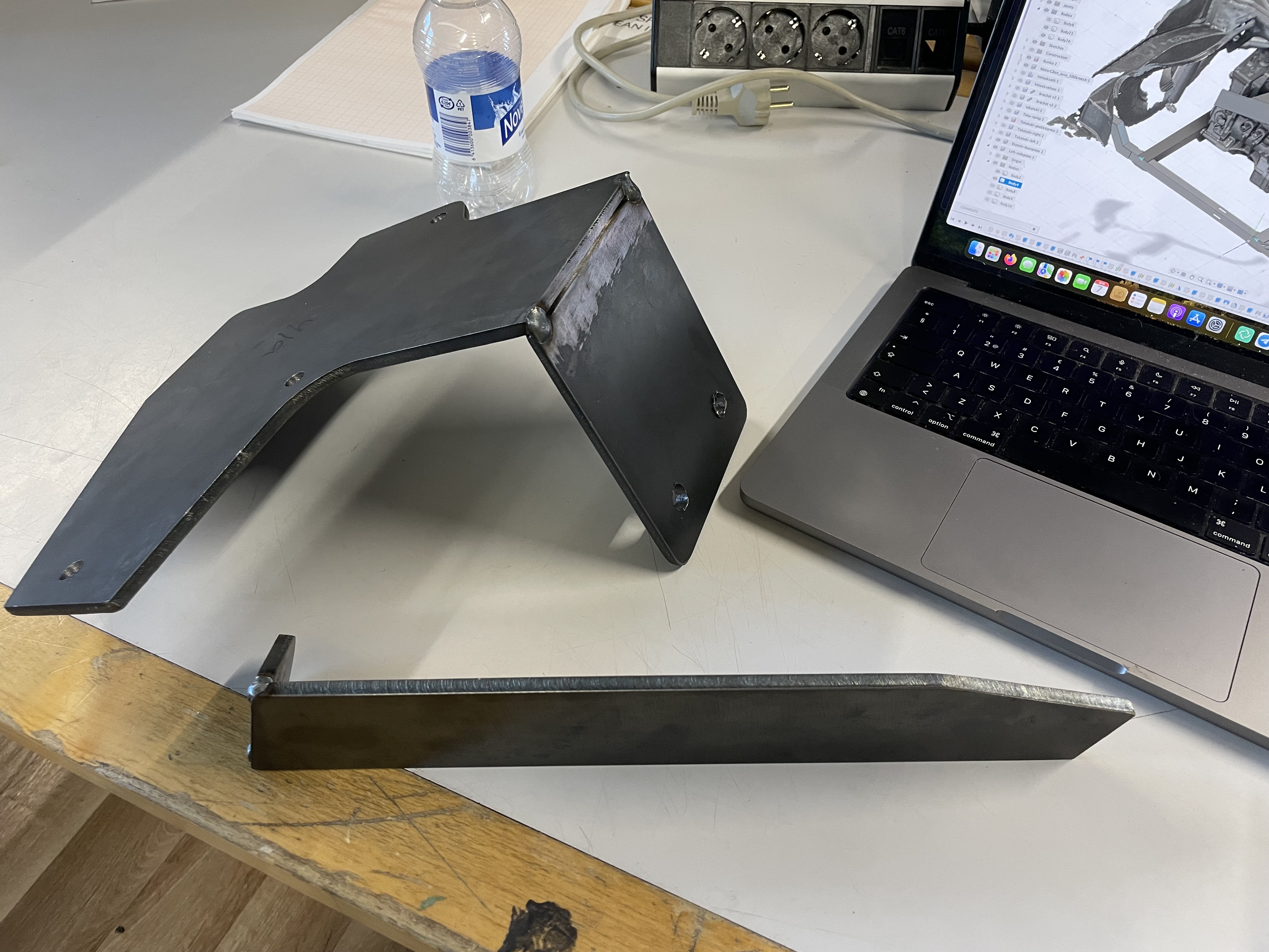
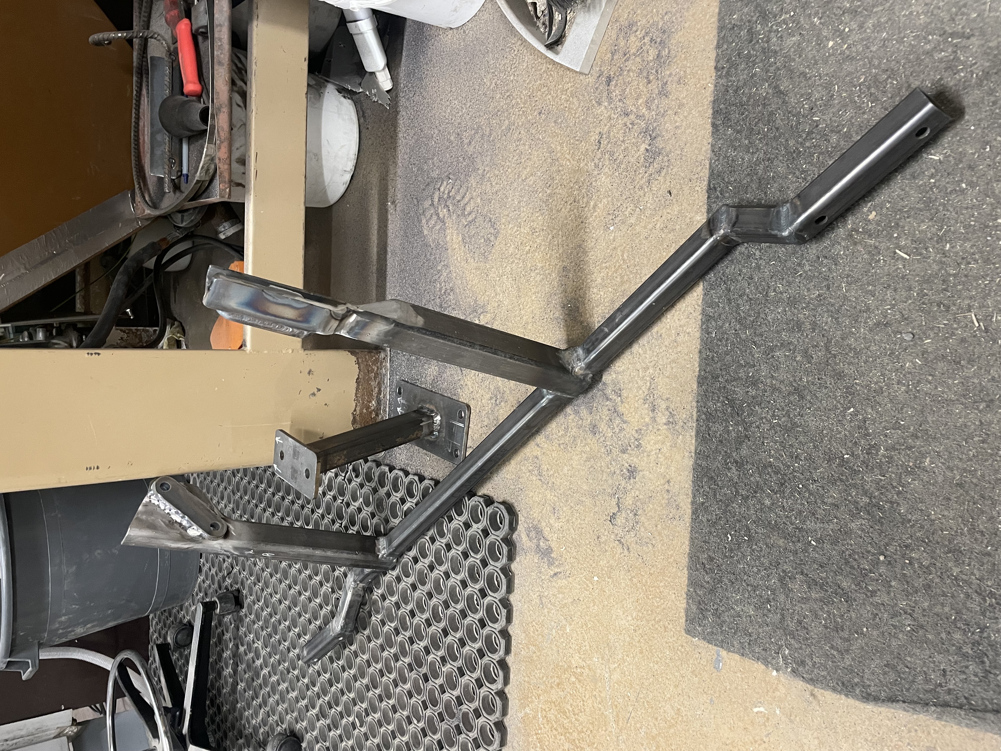
The upper mount is still on the table. I've plasmacut the parts from 6mm steel, just need to weld it together now.
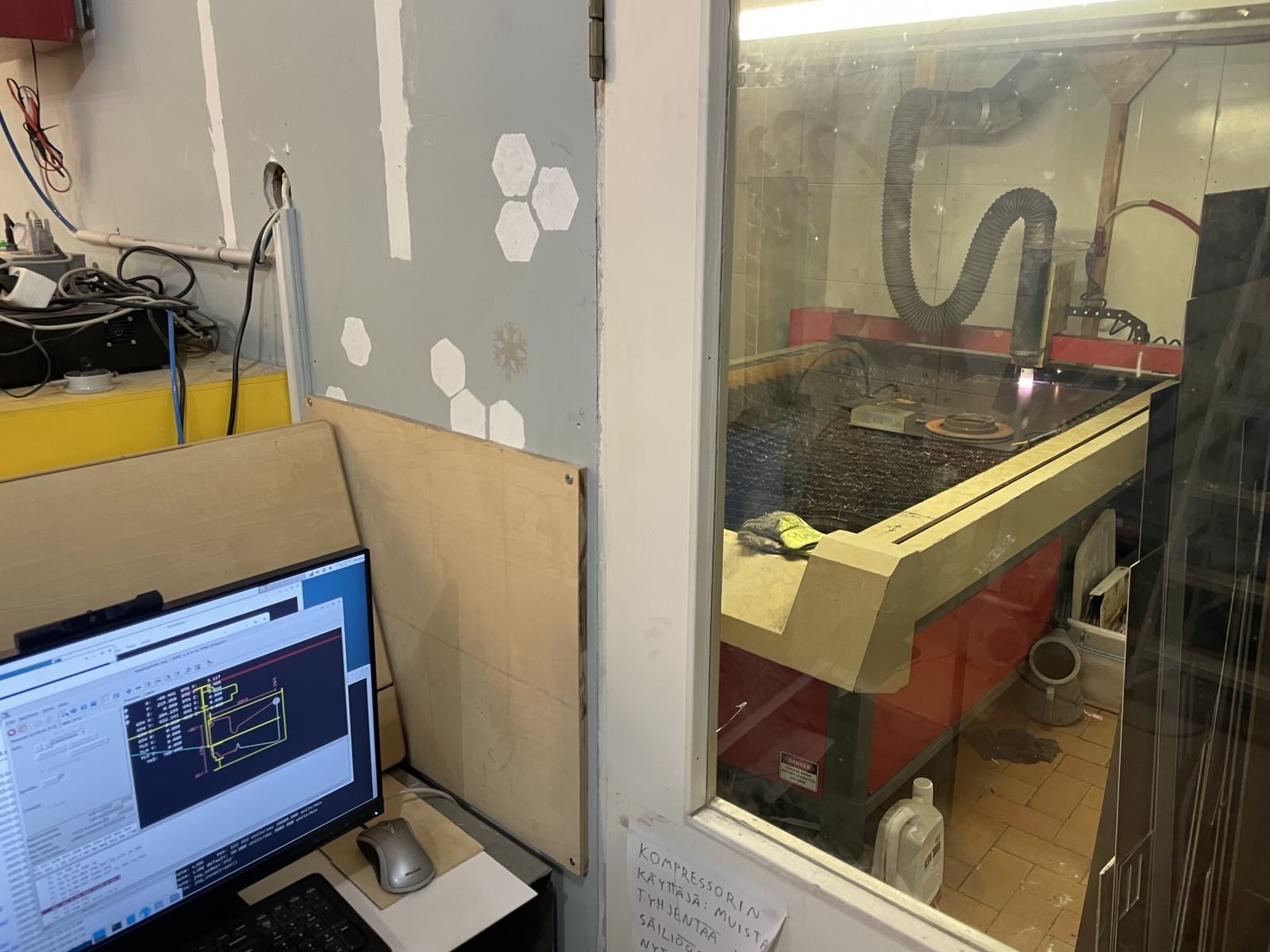
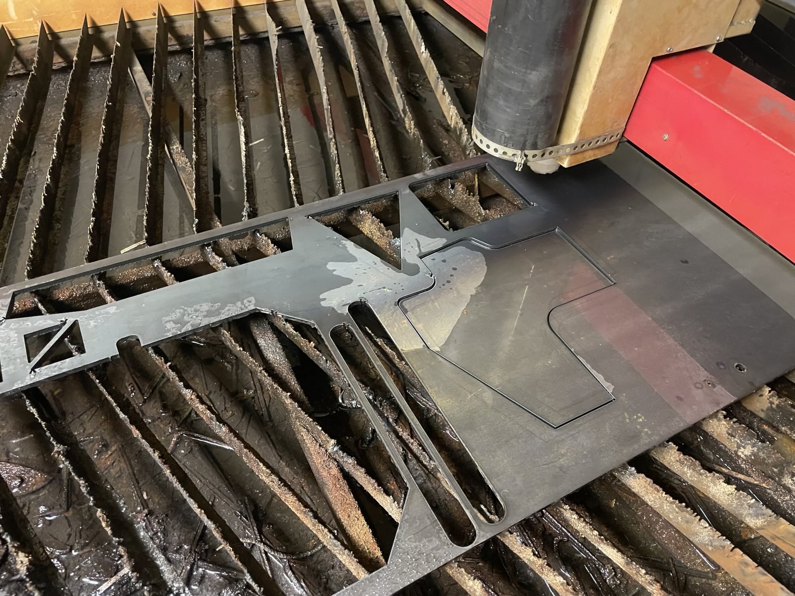
Summoning the 4th state of matter to cut steel with a press of a button feels like violating some laws of dark magic.
Some side quests too while procrastinating the scary stuff. Took measurements of the front kick panels and lasercut new ones.
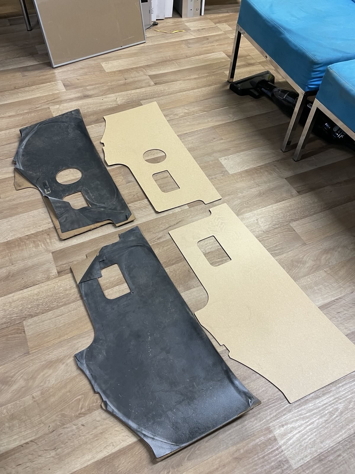
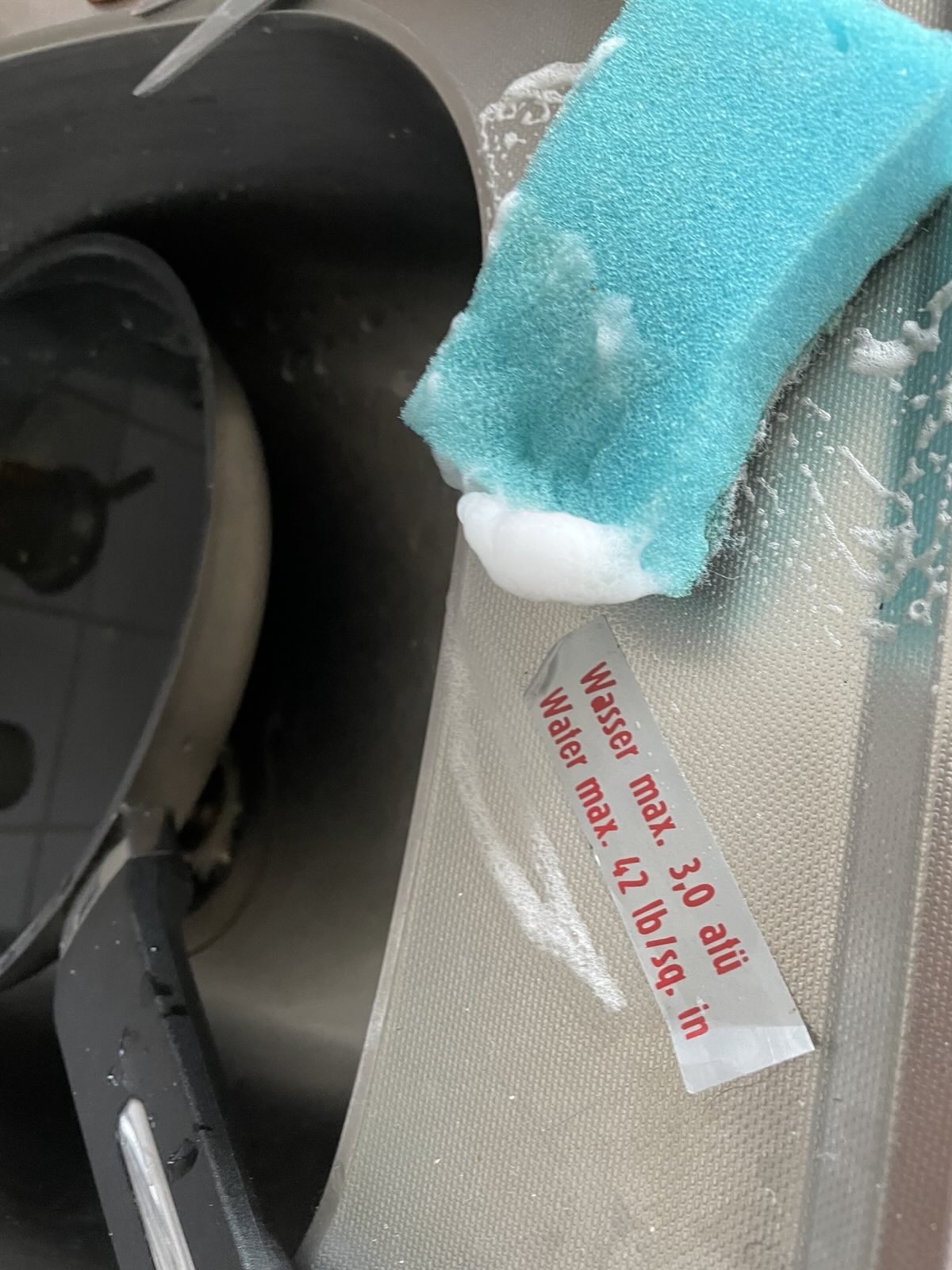
Of course saving and cleaning all the stickers from the old panels
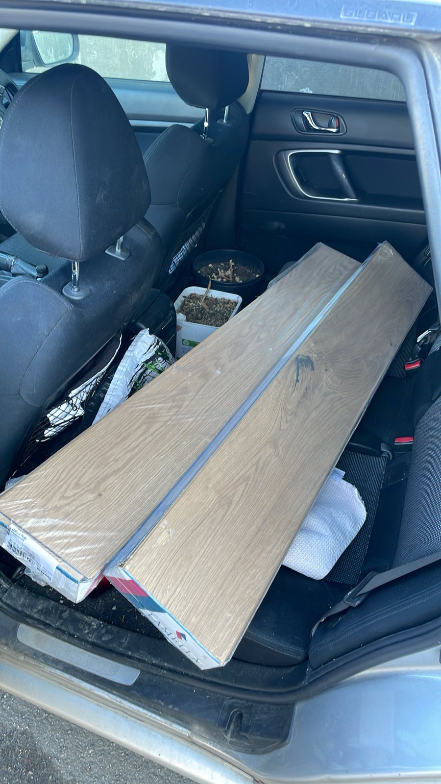
Happened to find a good deal for the interior flooring so oops, accidents happened.
Some kind of an update again
Next up is welding the 3rd motor mount, powder coating all of them and mounting properly after.
Re: [WIP] Voltswagen T2 -76
Posted: Sat Apr 05, 2025 12:51 am
by Bratitude
Hell yeah motor is in!
Are you using stock axles too or did you need longer ones?
m3 battery modules: the threaded terminal posts are quite long. I cut mine down so I was able to tightly pack modules together. And just made a clamp to junction the hv cable
Re: [WIP] Voltswagen T2 -76
Posted: Sat Apr 05, 2025 7:31 am
by Cera
Bratitude wrote: ↑Sat Apr 05, 2025 12:51 am
Hell yeah motor is in!
Are you using stock axles too or did you need longer ones?
m3 battery modules: the threaded terminal posts are quite long. I cut mine down so I was able to tightly pack modules together. And just made a clamp to junction the hv cable

Yeah stock CV's with your stubs and the EMPI adapters. I designed these mounts so that the angle of the CV's stays the same as in stock transaxle.
Wrt batteries, I'm aware that the terminal posts are long, I might end up doing the same and just cutting them.
I'm slightly worried about how I can get the M3 modules to work though. Semi-wishing I'd have picked easier ones for this first build
Re: [WIP] Voltswagen T2 -76
Posted: Mon Apr 07, 2025 12:14 pm
by PaulHeystee
Very nice motor mounting! Looks very professional!
by the way; I am working on a controller that can operate the small park acuator motor on the Leaf gearbox.
As soon as I am finished testing it I will place a post.
Re: [WIP] Voltswagen T2 -76
Posted: Mon Apr 07, 2025 3:45 pm
by Cera
PaulHeystee wrote: ↑Mon Apr 07, 2025 12:14 pm
Very nice motor mounting! Looks very professional!
by the way; I am working on a controller that can operate the small park acuator motor on the Leaf gearbox.
As soon as I am finished testing it I will place a post.
Thanks!

This would be great!! I've been thinking about how nice it'd be to get that to work for my shifter pattern (P-R-N-D) to make more sense.
Re: [WIP] Voltswagen T2 -76
Posted: Sat Apr 12, 2025 8:03 pm
by Cera
With our plasma cutter back in operation it was pretty quick to cut the pieces for the upper mount as well.
Tackweld together for test fitting.
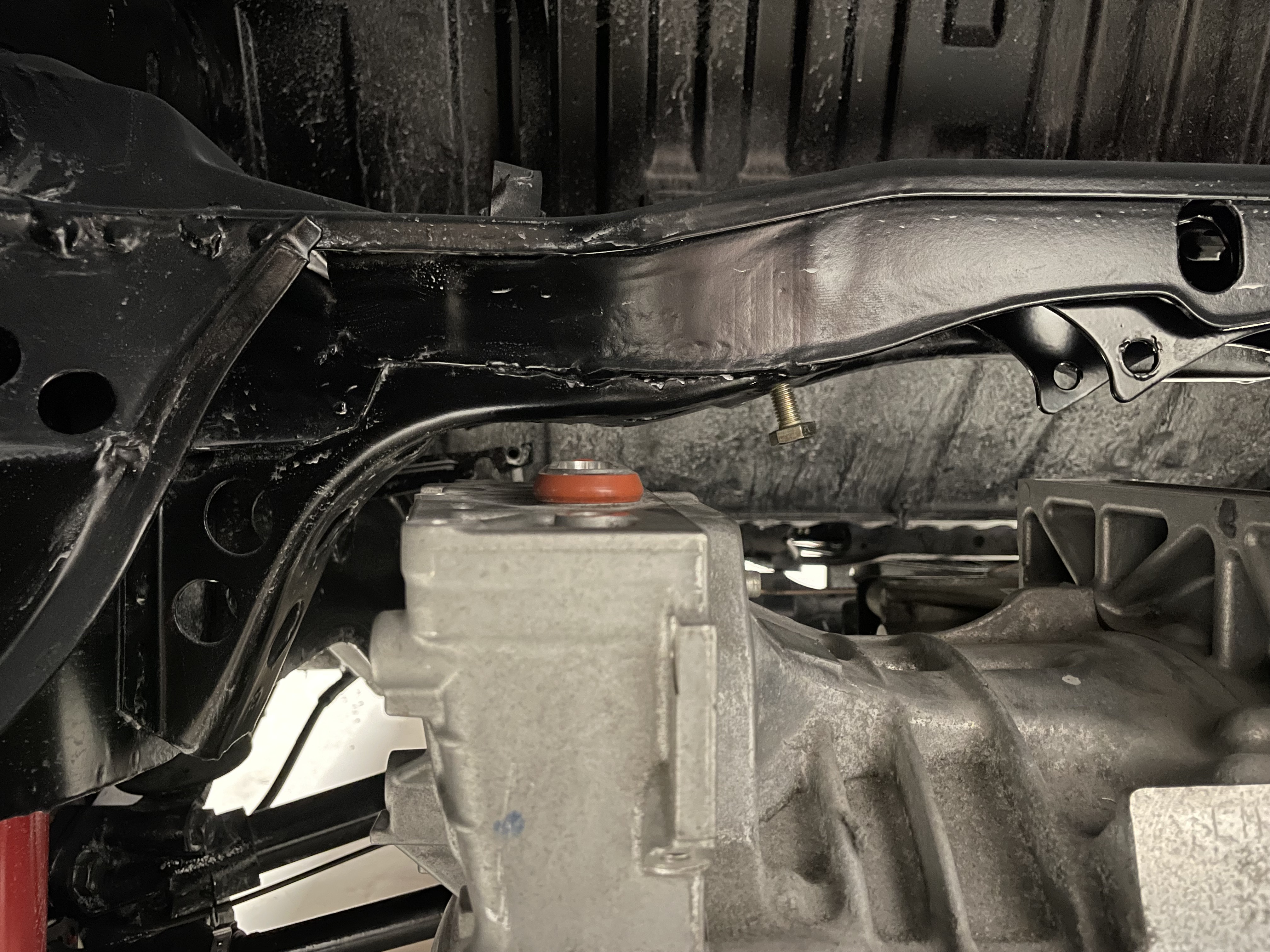
Confirmed it fits *almost* perfectly. Well. It fits, but something needs to be done to this water line which wasn't in my CAD files and therefore was ignored in planning.
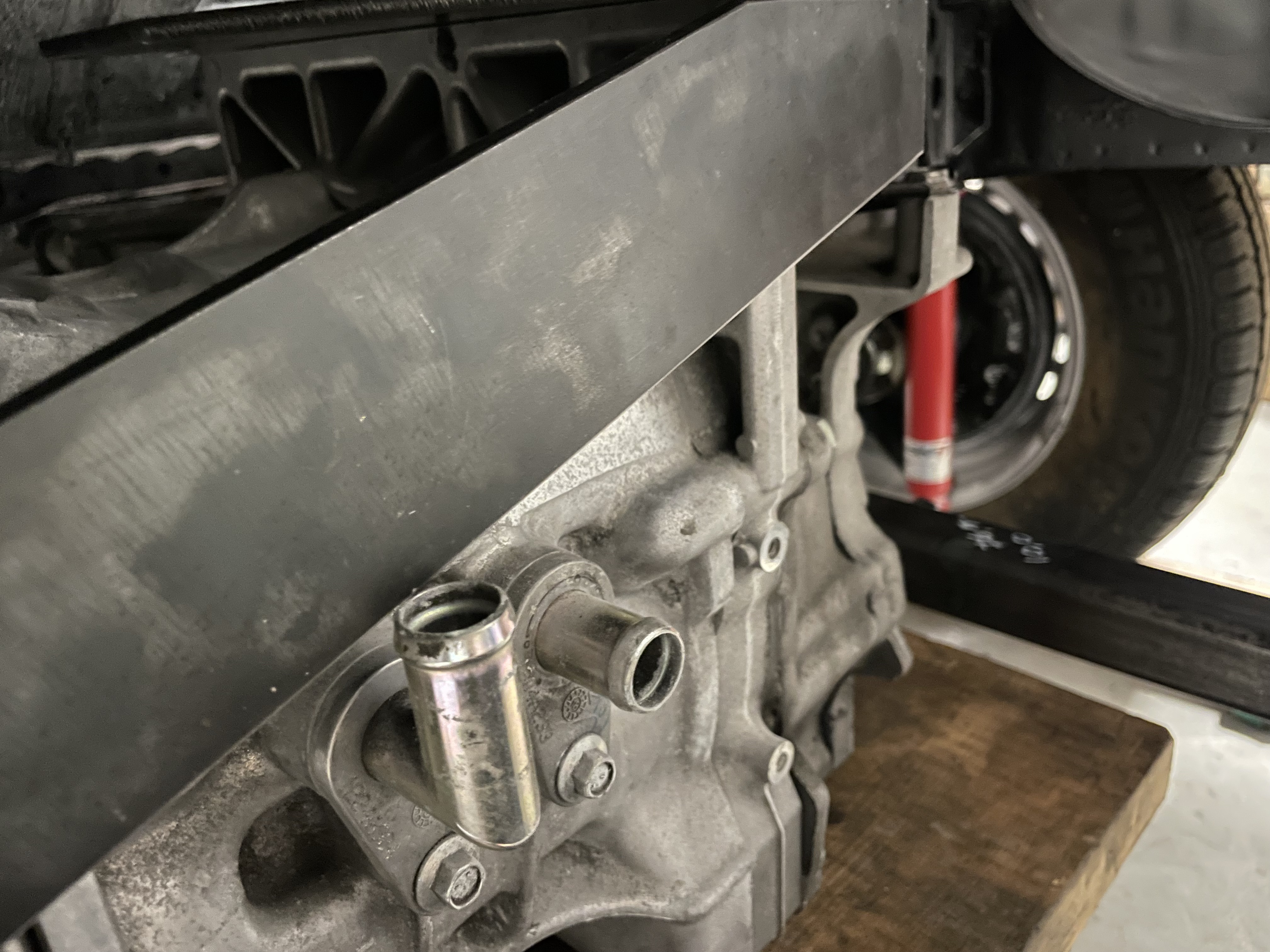
Hopefully can just rotate it a lil bit.
Anyway with that confirmed, I pulled out the front and rear mounts.
Some slight modifications (extra 10mm for compensating the error in measurements I made earlier)

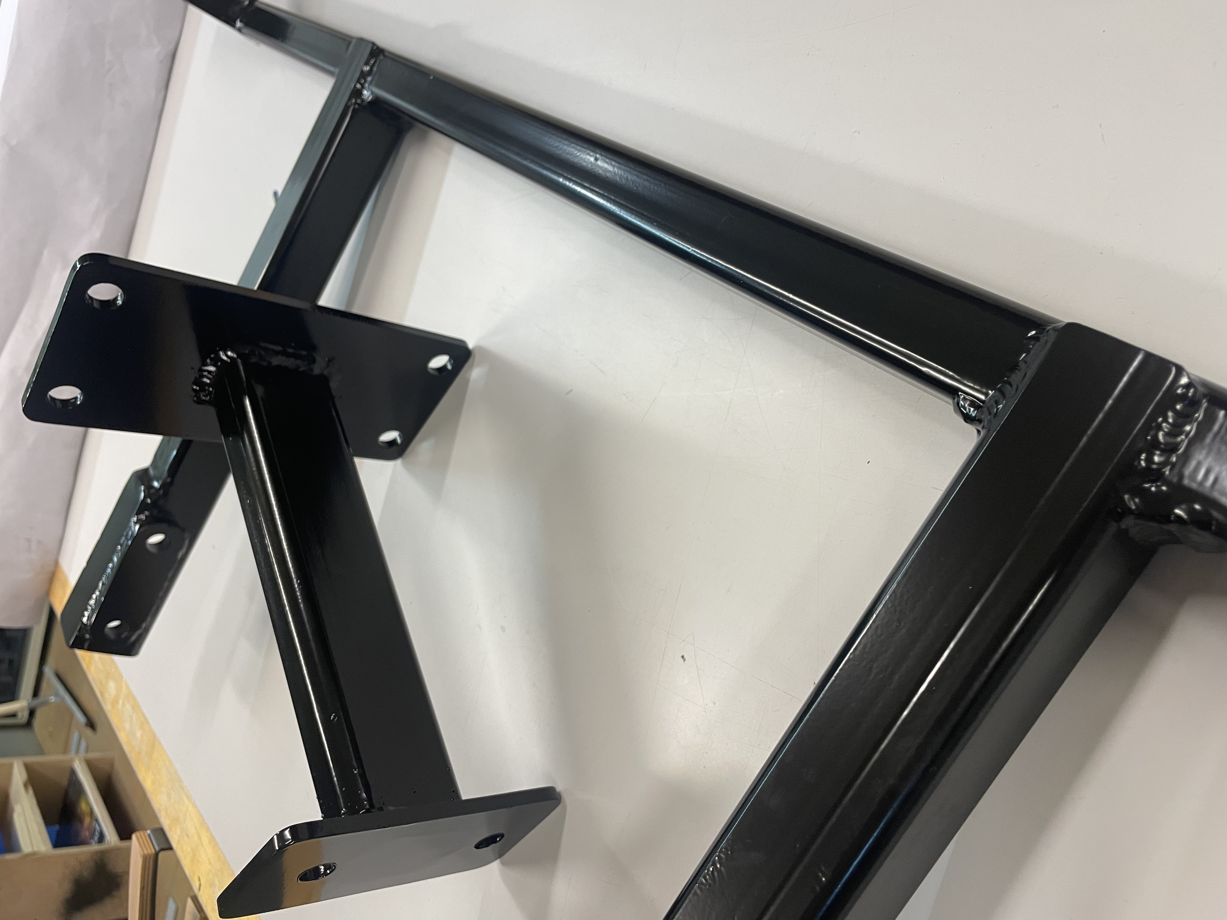
Then sandblasting
And powder coating

Making it look all professional, even if it ain't!
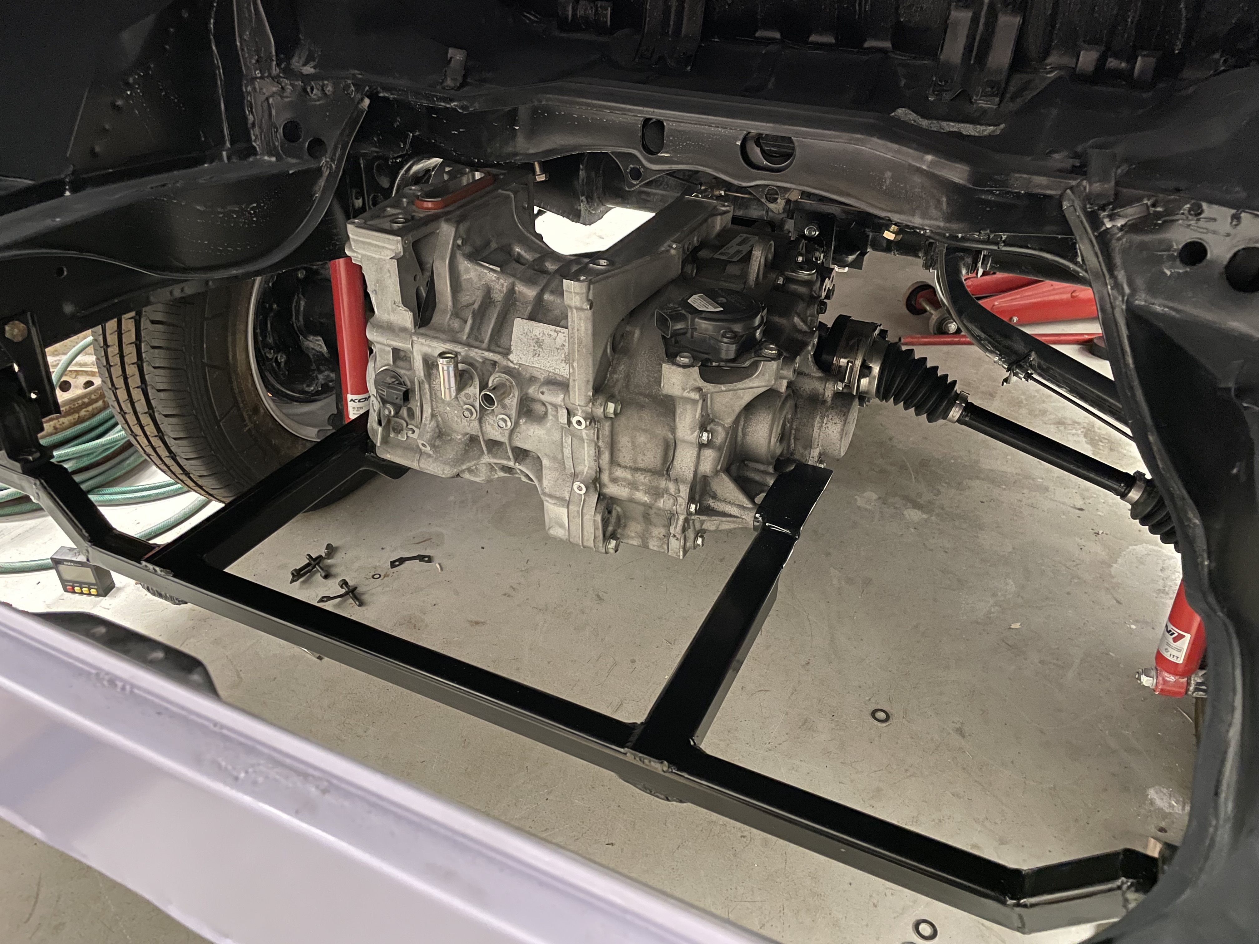
And back in the vehicle
looking neat.
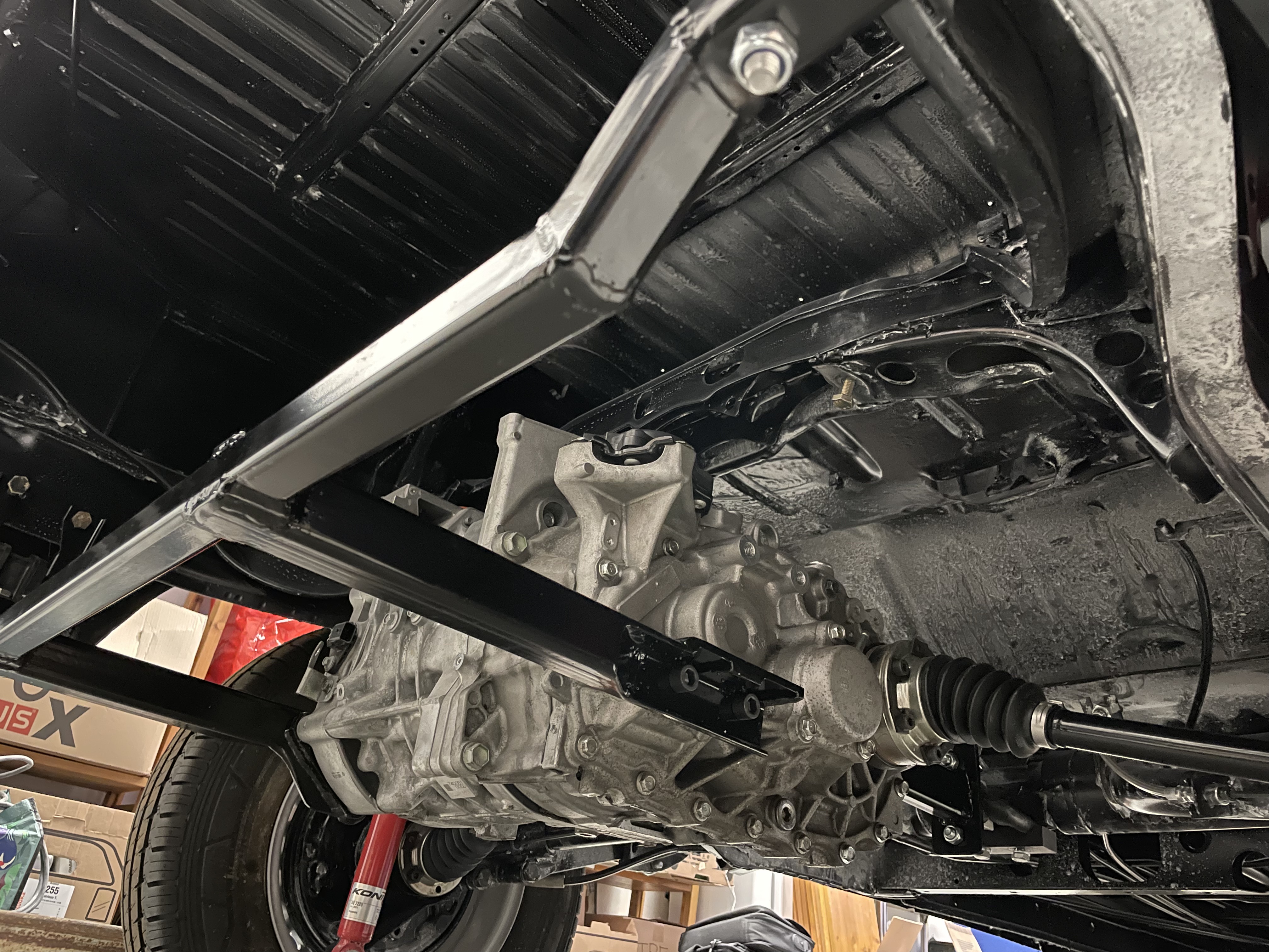
Still missing the upper mount but it's in for the same treatment soon. Meanwhile realizing some other problems for the future. This is slightly too close for comfort, I hope I'll still be able to run the phase wires to inverter so that they don't rub against the frame here. Some 3/4 of the connector is "in the open" and the rightmost 1/4th ends up under the crossbeam with approx. 15-20mm gap to it.
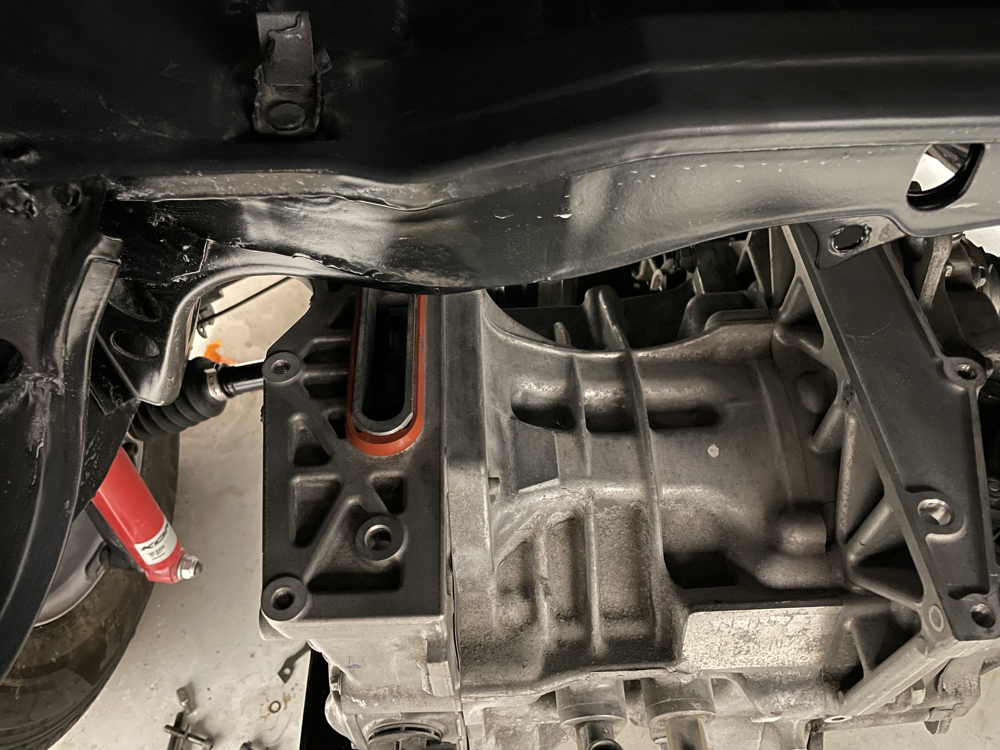
Ah well. I hope these don't end up being a bigger problem.
My plan was to mount the inverter on top of this beam anyway. There's a shelf where the former gas tank used to be, which is basically big empty area currently I'm planning to use for the inverter, HVJB, maybe something else too.
I'm tempted by the Tesla M3 PCS and the batteries, but darn the more I look at the other build threads, the more complex it seems. I should educate myself about BMS options and batman chips if I go that route I guess...
Ahh.. From one challenge to the next.
Re: [WIP] Voltswagen T2 -76
Posted: Sun Apr 13, 2025 6:34 am
by Jacobsmess
For the 3 phase connector, can you use the connection via the cover on the side with some 3d printed gland instead of the original?


 It's way too late for physics here.


