I have been building my car battery pack using the diyBMS.
This project was developed for diy powerwalls but i thought it would be great for my car.
Now that it's all working i have a few problems.
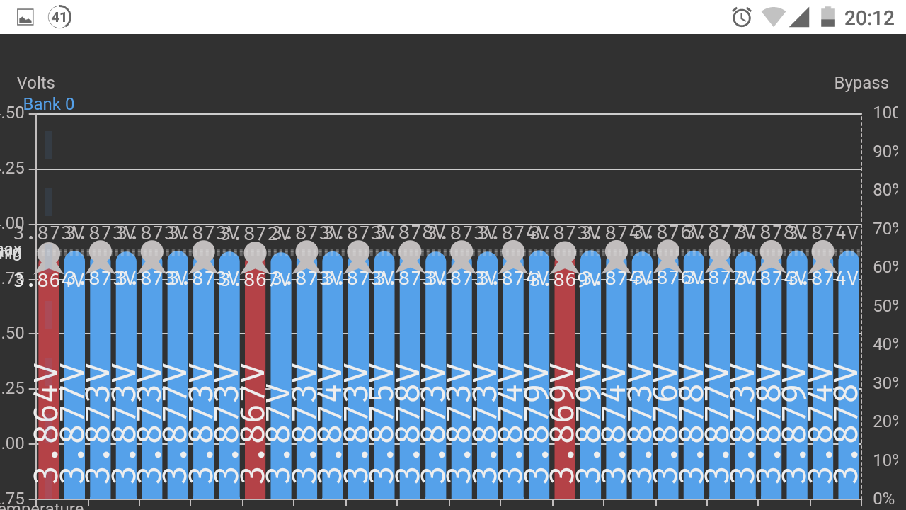
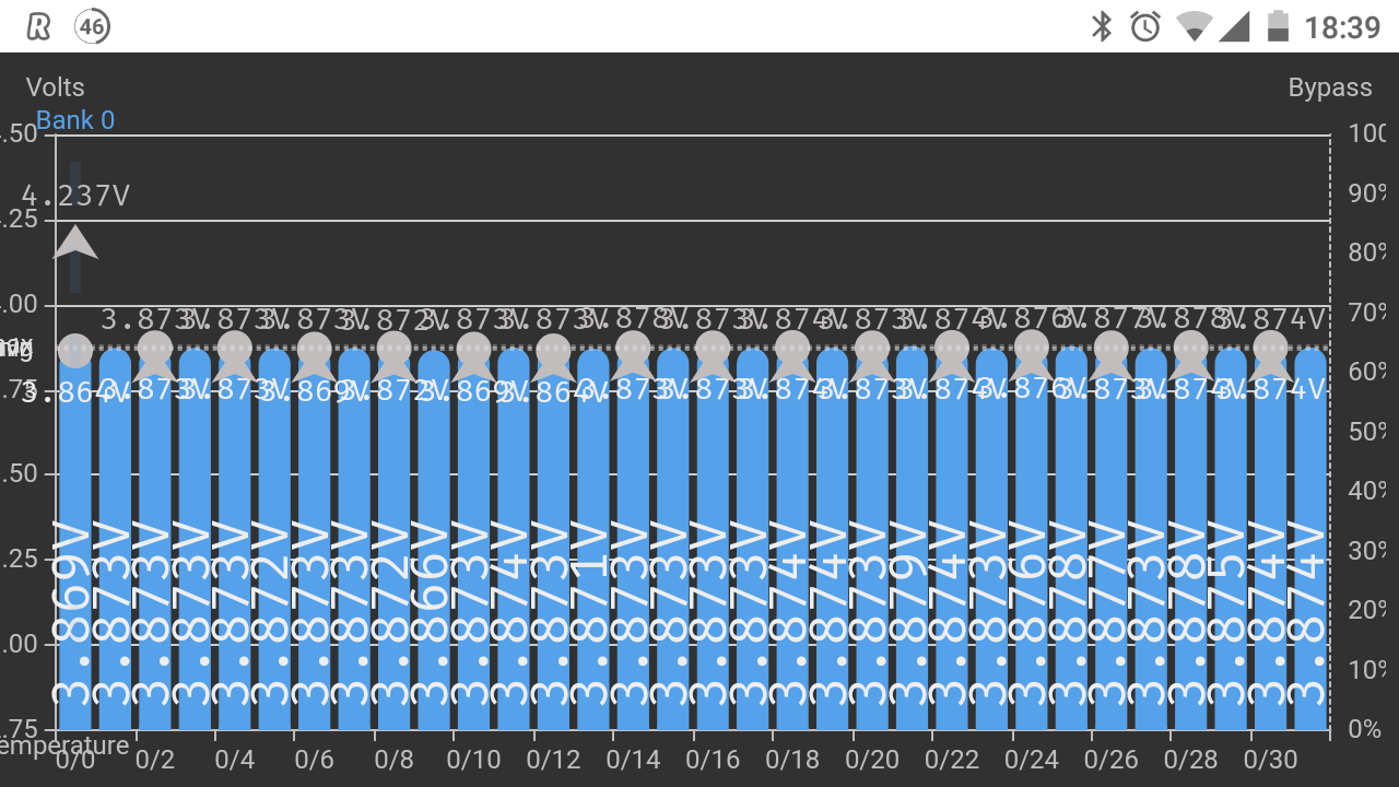
When i drive the voltages are very slow to show any variation, i thint it's every 6sec.
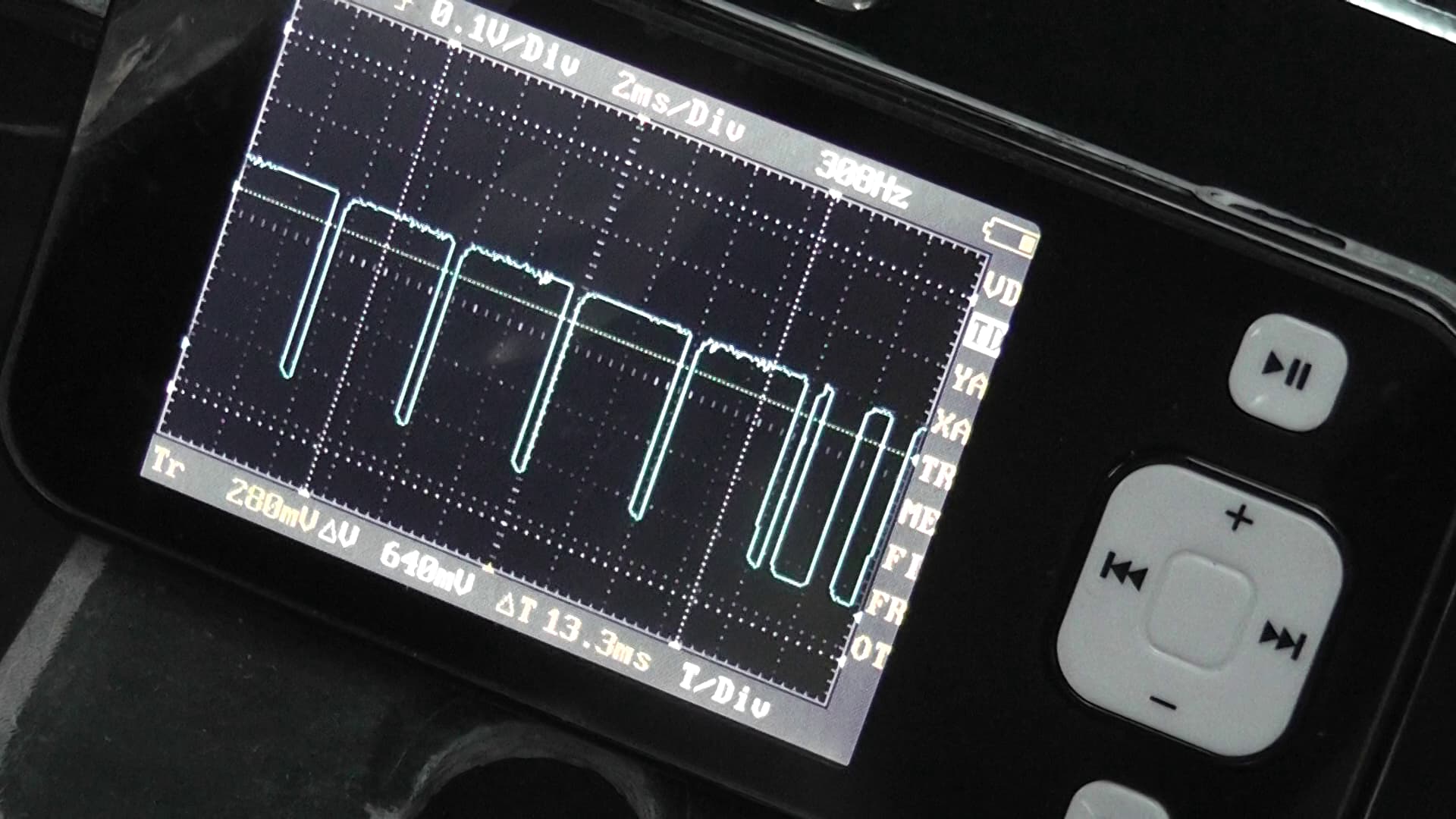
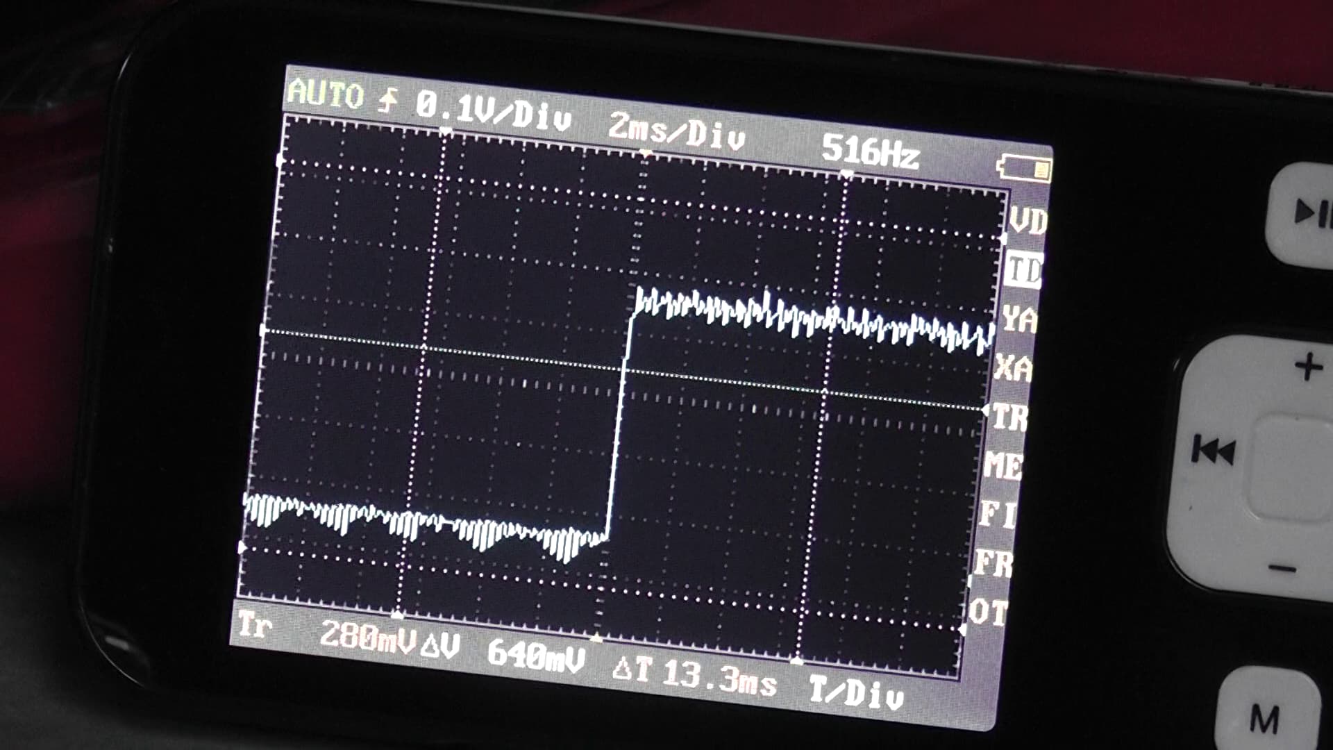
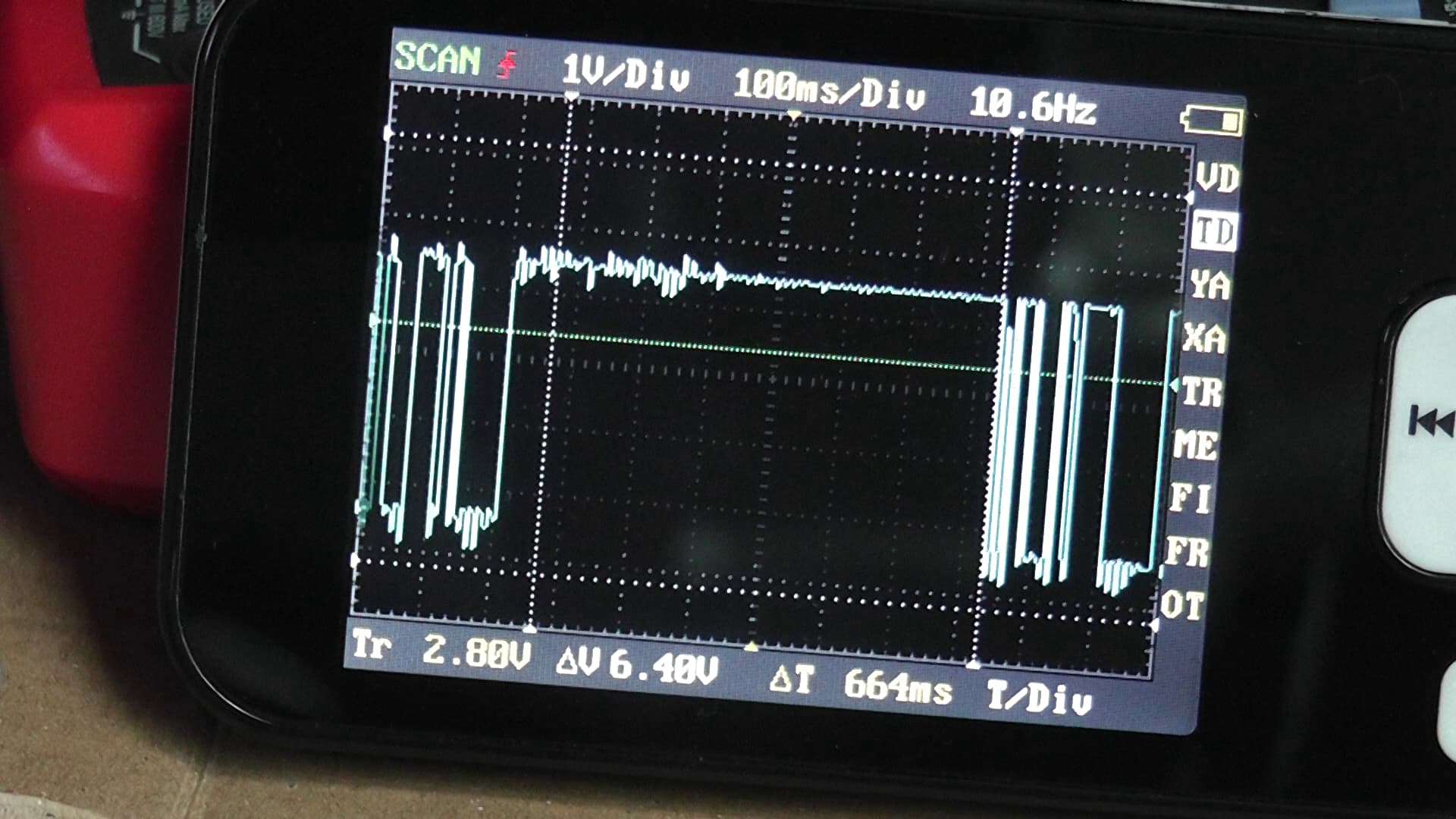
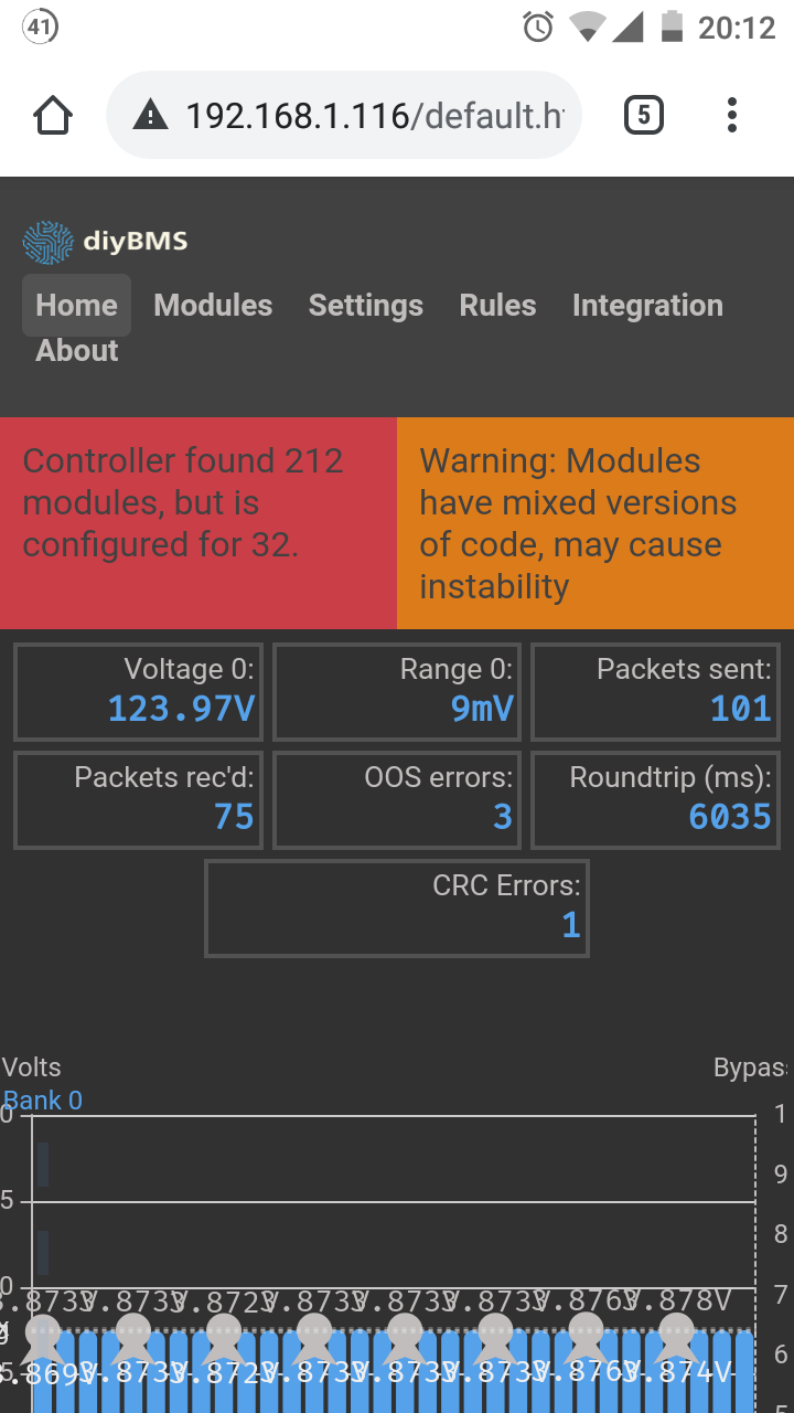
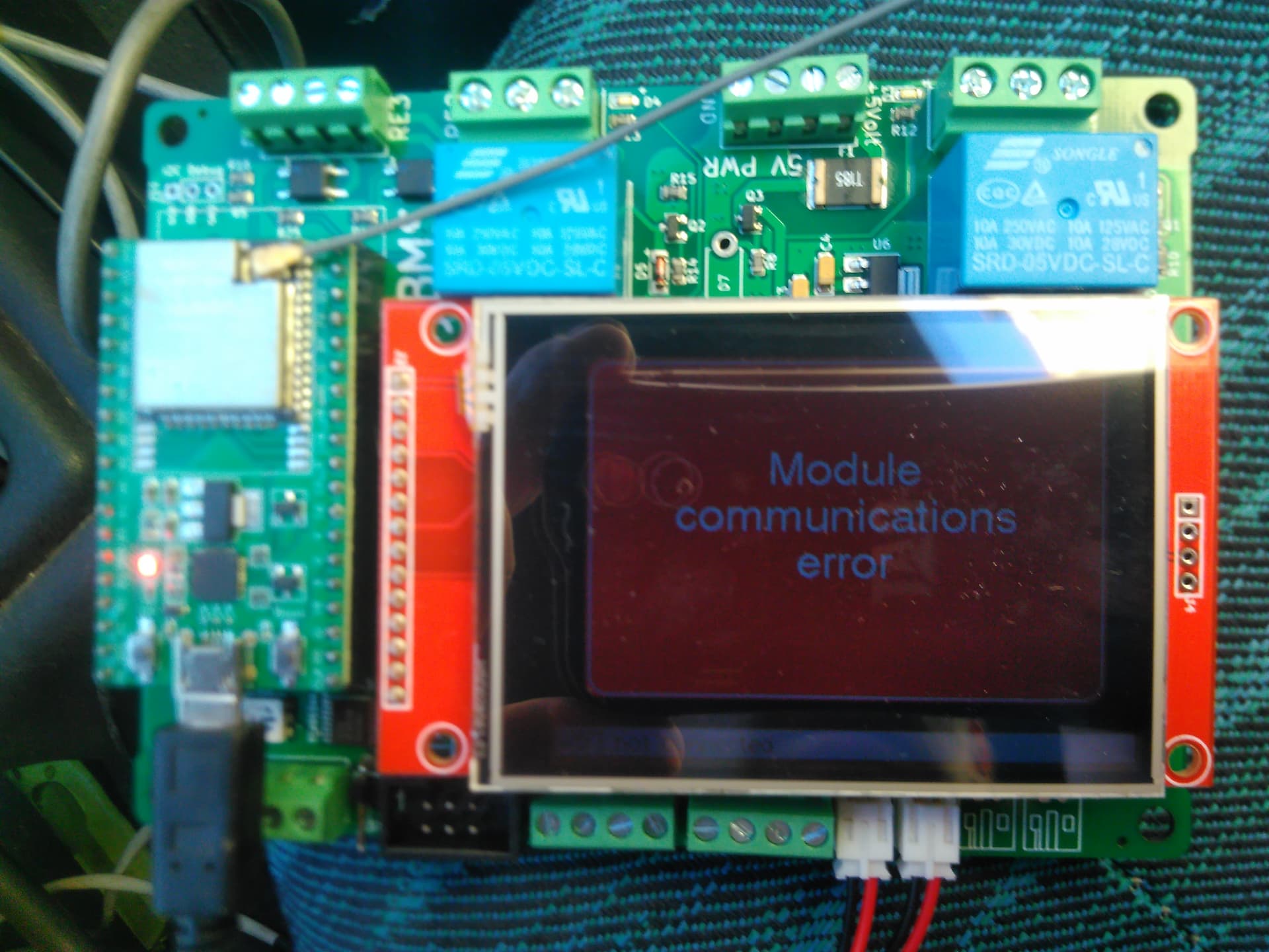
When i charge the modules go crazy and i lose all communication.
The voltages go from 3.8 to 4.2 but it's not possible as the batteries are 240Ah and i am charging at 3Ah or 14Ah.
so i have a 32s3p battery (https://www.facebook.com/106.Electric)
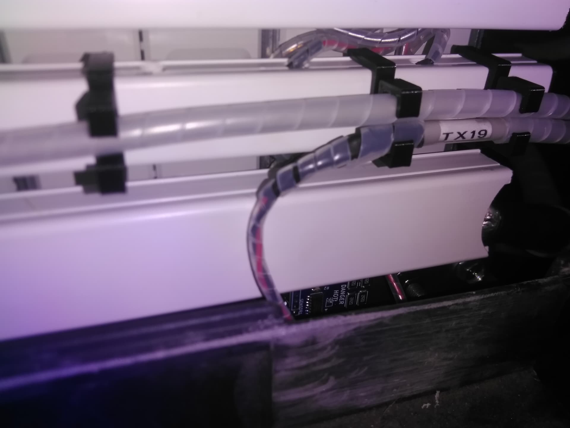
Each bms is conected in a way that all 3p have the same lenght of wire to it.
Also there are temperature probes screwed in the terminals but don't worry about that.
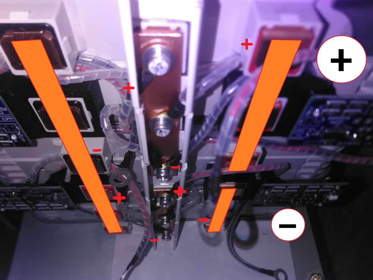
All the cables are twisted.
All the cables until the last 10cm (when they go to the modules) are shielded.
The shield is grounded to the car chassis (negative) close to the controller and at each of the 3 packs.
Any idea of what i can do next?
I can't charge the car but i can drive it
Should i give up and get the 4-channel BMS from johu?