I think we found out it is in fact a UVW encoder and all 3 phase leads were fed through one hall effect current sensor in the original inverter for that motor. Encoder has 3 signal wires that seem to produce 4 pulses each per full motor revolution although it seems pulses start and end at different motor positions with each signal wire. Is a software solution (or signal conversion) even possible for such an encoder with openinverter?
Prius Gen 3 Inverter Logic Board Support Thread
-
m.art.y
- Posts: 558
- Joined: Sat Jun 06, 2020 6:54 pm
- Location: UK
- Has thanked: 28 times
- Been thanked: 16 times
Re: Prius Gen 3 Inverter Logic Board Support Thread
-
Dylan Witt
- Posts: 116
- Joined: Sat Apr 18, 2020 4:23 am
- Location: Kentucky, USA
- Been thanked: 1 time
Re: Prius Gen 3 Inverter Logic Board Support Thread
Well Crap!!!!!!!!!
Openinverter FOC Tuning. i have drove my self crazy.
i hate guess work. wrote down wiring connections for the Prius Gen 3 to the P314 transmission for my electric mazda, now after finding the exciter wiring and resolver wiring, i now have tried over 16 different combinations for the resolver winding, anyways i keep getting a crazy 180-260 degree jump on the angle sensor of the open inverter gen three prius board, now my question, has anyone figured this wiring mess out?
-
m.art.y
- Posts: 558
- Joined: Sat Jun 06, 2020 6:54 pm
- Location: UK
- Has thanked: 28 times
- Been thanked: 16 times
Re: Prius Gen 3 Inverter Logic Board Support Thread
Have you watched Damien's video carefully? After you identify exciter windings (lower resistance ones) you only got 4 possible combinations left.Dylan Witt wrote: ↑Sun Nov 29, 2020 6:11 am Well Crap!!!!!!!!!
Openinverter FOC Tuning. i have drove my self crazy.
i hate guess work. wrote down wiring connections for the Prius Gen 3 to the P314 transmission for my electric mazda, now after finding the exciter wiring and resolver wiring, i now have tried over 16 different combinations for the resolver winding, anyways i keep getting a crazy 180-260 degree jump on the angle sensor of the open inverter gen three prius board, now my question, has anyone figured this wiring mess out?

Re: Prius Gen 3 Inverter Logic Board Support Thread
At the first I would be check resolver polpair in your inverter settings. (Hint: polpair=1 )Dylan Witt wrote: ↑Sun Nov 29, 2020 6:11 am Well Crap!!!!!!!!!
Openinverter FOC Tuning. i have drove my self crazy.
i hate guess work. wrote down wiring connections for the Prius Gen 3 to the P314 transmission for my electric mazda, now after finding the exciter wiring and resolver wiring, i now have tried over 16 different combinations for the resolver winding, anyways i keep getting a crazy 180-260 degree jump on the angle sensor of the open inverter gen three prius board, now my question, has anyone figured this wiring mess out?
My project is Electro-Tigra https://electrotransport.ru/ussr/index. ... 5.0#topmsg
Re: Prius Gen 3 Inverter Logic Board Support Thread
Is anybody try to start MG1 and MG2 power stages in parallel with six jumpers SJ1-6?
How connect three phases outputs? If I connect in parallel to regular outputs, then MG2 current will be measured with regular current sensors, but MG1 current sensors connect to Arduino and MG1 current stay not measured.
Is this problem may be fixed with MG2 current sensors calibration?
How connect three phases outputs? If I connect in parallel to regular outputs, then MG2 current will be measured with regular current sensors, but MG1 current sensors connect to Arduino and MG1 current stay not measured.
Is this problem may be fixed with MG2 current sensors calibration?
My project is Electro-Tigra https://electrotransport.ru/ussr/index. ... 5.0#topmsg
-
m.art.y
- Posts: 558
- Joined: Sat Jun 06, 2020 6:54 pm
- Location: UK
- Has thanked: 28 times
- Been thanked: 16 times
Re: Prius Gen 3 Inverter Logic Board Support Thread
Konstantin8818 had both MG1 and MG2 running at the same time, he posted youtube video about it. Maybe he could advise you?UStas wrote: ↑Wed Dec 02, 2020 11:22 pm Is anybody try to start MG1 and MG2 power stages in parallel with six jumpers SJ1-6?
How connect three phases outputs? If I connect in parallel to regular outputs, then MG2 current will be measured with regular current sensors, but MG1 current sensors connect to Arduino and MG1 current stay not measured.
Is this problem may be fixed with MG2 current sensors calibration?
-
m.art.y
- Posts: 558
- Joined: Sat Jun 06, 2020 6:54 pm
- Location: UK
- Has thanked: 28 times
- Been thanked: 16 times
Re: Prius Gen 3 Inverter Logic Board Support Thread
Anybody knows if there is some sort of firmware to run DCDC converter on the gen 3 Prius inverter? There is a section 'Charger' in the web interface. What is it for? Thanks 

Re: Prius Gen 3 Inverter Logic Board Support Thread
Sorry, but there are an AC motors, and I need control MGR (IPM motor) here need FOC and current sensor. Because a question is.
My project is Electro-Tigra https://electrotransport.ru/ussr/index. ... 5.0#topmsg
-
m.art.y
- Posts: 558
- Joined: Sat Jun 06, 2020 6:54 pm
- Location: UK
- Has thanked: 28 times
- Been thanked: 16 times
Re: Prius Gen 3 Inverter Logic Board Support Thread
Anybody knows if we still need to do pin swaping with the latest FOC firmware? Thanks 

-
Bigpie

- Posts: 1595
- Joined: Wed Apr 10, 2019 8:11 pm
- Location: South Yorkshire, UK
- Has thanked: 75 times
- Been thanked: 304 times
Re: Prius Gen 3 Inverter Logic Board Support Thread
You still need to pin swap, though in the latest firmware you can just select PWMOutput23.
One thing I've noticed is in the FOC tuning video Damien manually sets pinswap=5 but the the params file above and in the web interface it's set to 8.
One thing I've noticed is in the FOC tuning video Damien manually sets pinswap=5 but the the params file above and in the web interface it's set to 8.
VW Beetle 2003
Outlander front generator
Prius Gen 3 inverter (EVBMW logic board)
Outlander charger
3x Golf GTE batteries
Chademo Charging
Outlander water heater
Outlander front generator
Prius Gen 3 inverter (EVBMW logic board)
Outlander charger
3x Golf GTE batteries
Chademo Charging
Outlander water heater
-
Bigpie
- Posts: 1595
- Joined: Wed Apr 10, 2019 8:11 pm
- Location: South Yorkshire, UK
- Has thanked: 75 times
- Been thanked: 304 times
Re: Prius Gen 3 Inverter Logic Board Support Thread
I've been struggling to get my motor to rotate the last few days, after it previously working, same settings as before so I've re-run through the FOC video.
Resolver looks good.
Same arrangement as before, I've gone with combination 3.
Lightbulb is bypassed after pre-charge.
Setting syncofs back to 0 and entering 3 amps in manualid, a bit of squealing, same for 6,9, 10.
I tried syncofs 10000, 20000, 30000, 40000, 50000, 6000 with the same result.
Also tried setting manualid to 0.1 and manualiq to 3 at both syncofs 0 and 46550 (which I previously got through the procedure)
Also tried the other motor, same problem and I've tried switching back to sine firmware to run in manual mode and no longer starts to turn?
Any pointers as to where to look and what I could have messed up?
Resolver looks good.
Lightbulb is bypassed after pre-charge.
Setting syncofs back to 0 and entering 3 amps in manualid, a bit of squealing, same for 6,9, 10.
I tried syncofs 10000, 20000, 30000, 40000, 50000, 6000 with the same result.
Also tried setting manualid to 0.1 and manualiq to 3 at both syncofs 0 and 46550 (which I previously got through the procedure)
Also tried the other motor, same problem and I've tried switching back to sine firmware to run in manual mode and no longer starts to turn?
Any pointers as to where to look and what I could have messed up?
VW Beetle 2003
Outlander front generator
Prius Gen 3 inverter (EVBMW logic board)
Outlander charger
3x Golf GTE batteries
Chademo Charging
Outlander water heater
Outlander front generator
Prius Gen 3 inverter (EVBMW logic board)
Outlander charger
3x Golf GTE batteries
Chademo Charging
Outlander water heater
-
Jack Bauer

- Posts: 3563
- Joined: Wed Dec 12, 2018 5:24 pm
- Location: Ireland
- Has thanked: 1 time
- Been thanked: 87 times
- Contact:
Re: Prius Gen 3 Inverter Logic Board Support Thread
Inverter temperature? Deadtime setting? inverter cooling? pwm freq?
I'm going to need a hacksaw
-
Bigpie
- Posts: 1595
- Joined: Wed Apr 10, 2019 8:11 pm
- Location: South Yorkshire, UK
- Has thanked: 75 times
- Been thanked: 304 times
Re: Prius Gen 3 Inverter Logic Board Support Thread
All other parameters are from the file you posted a few posts up. There's some current flowing, if I turn lightbulb back on it gets progressively brighter with more current.
VW Beetle 2003
Outlander front generator
Prius Gen 3 inverter (EVBMW logic board)
Outlander charger
3x Golf GTE batteries
Chademo Charging
Outlander water heater
Outlander front generator
Prius Gen 3 inverter (EVBMW logic board)
Outlander charger
3x Golf GTE batteries
Chademo Charging
Outlander water heater
-
Jack Bauer
- Posts: 3563
- Joined: Wed Dec 12, 2018 5:24 pm
- Location: Ireland
- Has thanked: 1 time
- Been thanked: 87 times
- Contact:
Re: Prius Gen 3 Inverter Logic Board Support Thread
disconnect the motor windings and test again. does the bulb glow? it shouldnt. Watch the tmphs. if it gets too high Johannes will limit current. If it gets higher the Toyota engineers will limit current. Lots of little gotchas in this stuff.
I'm going to need a hacksaw
-
m.art.y
- Posts: 558
- Joined: Sat Jun 06, 2020 6:54 pm
- Location: UK
- Has thanked: 28 times
- Been thanked: 16 times
Re: Prius Gen 3 Inverter Logic Board Support Thread
Does FOC firmware has to have motor temp sensor connected as a must or is it optional?
-
Bigpie
- Posts: 1595
- Joined: Wed Apr 10, 2019 8:11 pm
- Location: South Yorkshire, UK
- Has thanked: 75 times
- Been thanked: 304 times
Re: Prius Gen 3 Inverter Logic Board Support Thread
The bulb doesn't glow with the motor phase wires disconnected. Temperature doesn't see to be an issue, though I'm pretty confident it's not reading the temperature correctly.Jack Bauer wrote: ↑Fri Dec 11, 2020 9:36 am disconnect the motor windings and test again. does the bulb glow? it shouldnt. Watch the tmphs. if it gets too high Johannes will limit current. If it gets higher the Toyota engineers will limit current. Lots of little gotchas in this stuff.
If I set syncofs to a value of 36000, previously a manualid of 3 would have it spinning clockwise according to my notes from tuning, it now doesn't with either motor.
With a syncofs of 46550, previously a manualid 0.1 and manualiq of 3 would have the motor spinning, again it now doesn't with either motor.
With some current flowing I cannot turn the shaft by hand.
VW Beetle 2003
Outlander front generator
Prius Gen 3 inverter (EVBMW logic board)
Outlander charger
3x Golf GTE batteries
Chademo Charging
Outlander water heater
Outlander front generator
Prius Gen 3 inverter (EVBMW logic board)
Outlander charger
3x Golf GTE batteries
Chademo Charging
Outlander water heater
-
Jack Bauer
- Posts: 3563
- Joined: Wed Dec 12, 2018 5:24 pm
- Location: Ireland
- Has thanked: 1 time
- Been thanked: 87 times
- Contact:
Re: Prius Gen 3 Inverter Logic Board Support Thread
So in this case we need to backtrack to something that works. go to sine firmware, disconnect resolver, set enc mode to single and do a manual run to check the inverter hardware, motor and wiring.
I'm going to need a hacksaw
-
Bigpie
- Posts: 1595
- Joined: Wed Apr 10, 2019 8:11 pm
- Location: South Yorkshire, UK
- Has thanked: 75 times
- Been thanked: 304 times
Re: Prius Gen 3 Inverter Logic Board Support Thread
I think I need to tear up my PhD in resolvers.
I had spinning with the sine firmware.
Although my notes says I had combination 3, I thought what the hell, combination 4 graph looks ok too. I wired up in that combination and it's spinning again.
Top tip, make accurate notes
Thanks for the help
I had spinning with the sine firmware.
Although my notes says I had combination 3, I thought what the hell, combination 4 graph looks ok too. I wired up in that combination and it's spinning again.
Top tip, make accurate notes
Thanks for the help
VW Beetle 2003
Outlander front generator
Prius Gen 3 inverter (EVBMW logic board)
Outlander charger
3x Golf GTE batteries
Chademo Charging
Outlander water heater
Outlander front generator
Prius Gen 3 inverter (EVBMW logic board)
Outlander charger
3x Golf GTE batteries
Chademo Charging
Outlander water heater
-
m.art.y
- Posts: 558
- Joined: Sat Jun 06, 2020 6:54 pm
- Location: UK
- Has thanked: 28 times
- Been thanked: 16 times
Re: Prius Gen 3 Inverter Logic Board Support Thread
This is what I have mounted:
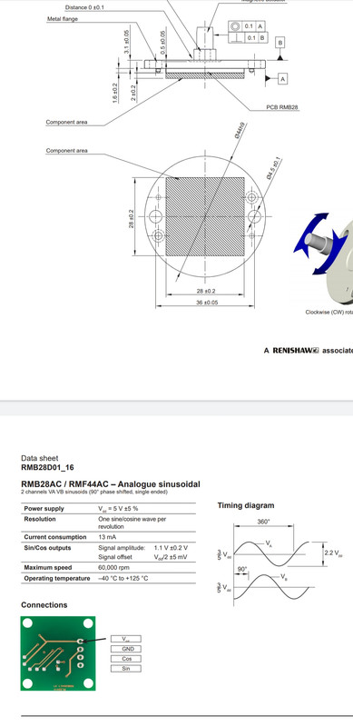
I get a reading now but it is not full 360 degrees but varies from around 120 to 240 when I spin the motor. Is the signal voltage wrong and how would I solve this?
-
Bigpie
- Posts: 1595
- Joined: Wed Apr 10, 2019 8:11 pm
- Location: South Yorkshire, UK
- Has thanked: 75 times
- Been thanked: 304 times
Re: Prius Gen 3 Inverter Logic Board Support Thread
Does it matter if when you've found what appears to be a good syncofs value that the motor spins anti clockwise with a manualid of 0.1 and manualq of 3 or does it need to spin clockwise for the signal of a good syncods?
VW Beetle 2003
Outlander front generator
Prius Gen 3 inverter (EVBMW logic board)
Outlander charger
3x Golf GTE batteries
Chademo Charging
Outlander water heater
Outlander front generator
Prius Gen 3 inverter (EVBMW logic board)
Outlander charger
3x Golf GTE batteries
Chademo Charging
Outlander water heater
-
Jack Bauer
- Posts: 3563
- Joined: Wed Dec 12, 2018 5:24 pm
- Location: Ireland
- Has thanked: 1 time
- Been thanked: 87 times
- Contact:
Re: Prius Gen 3 Inverter Logic Board Support Thread
Nope direction is unimportant in this case. Yeah you gotta watch the steps. FOC is unforgiving of mistakes. I should know:)
I'm going to need a hacksaw
-
bobby_come_lately

- Posts: 466
- Joined: Sun May 03, 2020 5:39 am
- Location: Manchester, UK
- Has thanked: 37 times
- Been thanked: 39 times
- Contact:
Re: Prius Gen 3 Inverter Logic Board Support Thread
Just had a fun moment setting my inverter up. Was following the FOC instructions so started inverter in manual mode and started to rotate the spindle to check angle. To my great surprise the motor started spinning. Before I could shut it down, there was then a pop and some magic smoke came out of my junction box (BMW S-Box). Pre-charge resistor has gone bye-bye. Thankfully everything else looks fine.
Clearly the main contactor wasn't closed and it was drawing current through the pre-charge relay. But manualiq and manualid were both zero and I can't work out why it was even trying to spin?
It was freshly flashed firmware, and I had uploaded @Bigpie's parameters from the database. But other than that, hadn't done anything other than hit 'Start in Manual Mode' and opened up the plot to check angle.
Working around it and have a replacement resistor on the way, but interested if anyone knows what I did wrong.
-
Jack Bauer
- Posts: 3563
- Joined: Wed Dec 12, 2018 5:24 pm
- Location: Ireland
- Has thanked: 1 time
- Been thanked: 87 times
- Contact:
Re: Prius Gen 3 Inverter Logic Board Support Thread
So foc is always looking to control current. Kinda it's one true mission in life. I'm guessing you didnt have the resolver offset setup? Anyway as you rotated the motor the mini Johannes brain said : hmmm...motor turning I'd better send some current into the stator in response to this. But as the resolver offset was wrong the current went into the wrong place which started pulling the rotor around, causing the mini brain to inject more current and so on:)
I'm going to need a hacksaw
-
bobby_come_lately
- Posts: 466
- Joined: Sun May 03, 2020 5:39 am
- Location: Manchester, UK
- Has thanked: 37 times
- Been thanked: 39 times
- Contact:
Re: Prius Gen 3 Inverter Logic Board Support Thread
Aha! Brilliant. Thank you. I understand now.Jack Bauer wrote: ↑Thu Jan 14, 2021 5:48 pm So foc is always looking to control current. Kinda it's one true mission in life. I'm guessing you didnt have the resolver offset setup? Anyway as you rotated the motor the mini Johannes brain said : hmmm...motor turning I'd better send some current into the stator in response to this. But as the resolver offset was wrong the current went into the wrong place which started pulling the rotor around, causing the mini brain to inject more current and so on:)
-
Bigpie
- Posts: 1595
- Joined: Wed Apr 10, 2019 8:11 pm
- Location: South Yorkshire, UK
- Has thanked: 75 times
- Been thanked: 304 times
Re: Prius Gen 3 Inverter Logic Board Support Thread
I'm having an issue with one of the MG1 current sensors. The Atmega pin A5 is held at 5v when no current, where as A4 is at around 2.5v as expected. Unplugging the current sensor sees A5 dropping to 0v. I get the same behaviour with the current sensor from another gen3 inverter plugged in.
Anyone able to offer a suggestion as to what else to look at?
Anyone able to offer a suggestion as to what else to look at?
VW Beetle 2003
Outlander front generator
Prius Gen 3 inverter (EVBMW logic board)
Outlander charger
3x Golf GTE batteries
Chademo Charging
Outlander water heater
Outlander front generator
Prius Gen 3 inverter (EVBMW logic board)
Outlander charger
3x Golf GTE batteries
Chademo Charging
Outlander water heater