6x6 Max
-
Kevin Sharpe

- Posts: 1345
- Joined: Fri Dec 14, 2018 9:24 pm
- Location: Ireland and US
- Been thanked: 4 times
Re: 6x6 Max
I've moved this thread into 'projects' because 'general' is getting unmanageable
This is a personal post and I disclaim all responsibility for any loss or damage which any person may suffer from reliance on the information and material in this post or any opinion, conclusion or recommendation in the information and material.
-
kiwifiat
- Posts: 99
- Joined: Sat Dec 22, 2018 9:39 pm
- Location: Vancouver, Canada
- Been thanked: 10 times
Re: Introduction and a few basic questions.
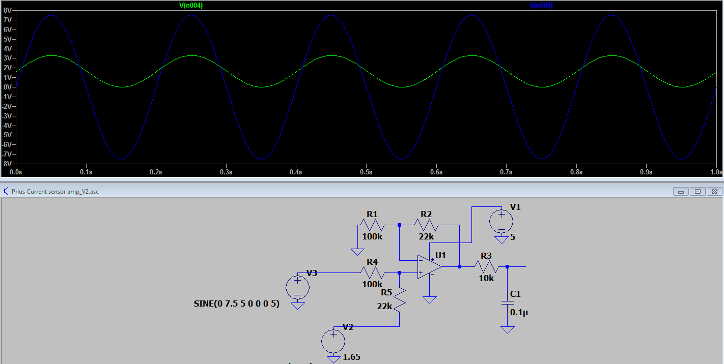
The circuit TheSilverBuick posted is for level shifting the Prius current sensors so they are compatible with the ADC converters on the STM32.jap wrote: ↑Mon Jul 20, 2020 2:33 pm Sorry, can't help with component values, but here is the schematic from johu's github:
res.jpg
Doesn't seem to be connected to any STM pin, wonder what that pin marked as "exciter" does on blue pill.. Anyway, maybe these posts would be better of under the appropriate thread.
TheSilverBuick can you please clarify if you are trying to build a current sensor conditioner or a resolver driver?
-
TheSilverBuick
- Posts: 187
- Joined: Mon Jun 08, 2020 5:01 pm
- Location: Nevada, United States
- Has thanked: 3 times
- Been thanked: 1 time
Re: 6x6 Max
The answer is both.
The obsolete Damien blue pill board for the Gen2 Prius inverter did not have a resolver exciter circuit, and the two current inputs cannot take the Toyota outputs directly, so need to be conditioned.
The voltage divider circuit looks straight forward enough, but the resolver exciter/driver schematic looks daunting for my skill level. I'm mulling over attempting it versus simply purchasing a Yaris board for my other inverter.
Need to learn. Starting from the basics.
-
kiwifiat
- Posts: 99
- Joined: Sat Dec 22, 2018 9:39 pm
- Location: Vancouver, Canada
- Been thanked: 10 times
Re: 6x6 Max
Contact Arber333, he designed a board for the resolver exciter/driver and he may still have some bare boards for sale. Johu posted an updated variation that eliminated the voltage reference I used in my design for the current sensor conditioning. I would use his schematic.TheSilverBuick wrote: ↑Thu Jul 23, 2020 5:06 am The answer is both.
The obsolete Damien blue pill board for the Gen2 Prius inverter did not have a resolver exciter circuit, and the two current inputs cannot take the Toyota outputs directly, so need to be conditioned.
The voltage divider circuit looks straight forward enough, but the resolver exciter/driver schematic looks daunting for my skill level. I'm mulling over attempting it versus simply purchasing a Yaris board for my other inverter.
-
TheSilverBuick
- Posts: 187
- Joined: Mon Jun 08, 2020 5:01 pm
- Location: Nevada, United States
- Has thanked: 3 times
- Been thanked: 1 time
Re: 6x6 Max
So after some thought and more reading, I'm still going to try my hand at the blue pill board with the Gen2 prius inverter and toyota MGR.
I've made the order to Digikey for the parts, have an STM32 chip and programmer on the way. I got the Wifi chip a while back. Arber333 says he has one more exciter board, so working on getting it.
Now the remaining questions on the voltage divider for the two current sensors that I've bolded below. Thanks!
Side note, I've picked up a 30v PSU and dug out an old oscilloscope that I had stuck in a closet for ever. Waiting on some new leads to see if it still works.TheSilverBuick wrote: ↑Mon Jul 20, 2020 12:04 pm Two questions on the circuit posted by kiwifiat, what is the part number for U1? And what wattages are recommended? I would think lower if fine in this application, but not certain. It is also referenced later that C1's rating needs to go from 1nF to 100nF.
kiwifiat wrote: ↑Thu Apr 16, 2020 4:16 pm The Prius Gen2 current sensors are bipolar 15Vp-p, not 10V or 7.1V. Use whatever you like as the 1.65V reference, what is critical is the OP amp output does not saturate as in the case of FOC accuracy of the current input is important to the control algorithm :
Need to learn. Starting from the basics.
-
Isaac96
- Posts: 656
- Joined: Sat Oct 05, 2019 6:50 pm
- Location: Northern California, USA
- Been thanked: 1 time
- Contact:
Re: 6x6 Max
I didn't design that circuit, nor do I often use op amps. But I'd get an LM324 - it's a quad op amp (and you need at least 2 for your sensors). It has good input voltage range so you should be fine.
-Isaac
-Isaac
-
TheSilverBuick
- Posts: 187
- Joined: Mon Jun 08, 2020 5:01 pm
- Location: Nevada, United States
- Has thanked: 3 times
- Been thanked: 1 time
Re: 6x6 Max
Thank you!
So with that chip, I would build two sets of circuits, each passing through the single chip, effectively utilizing half the LM324? That sounds straightforward enough.
Need to learn. Starting from the basics.
-
Isaac96
- Posts: 656
- Joined: Sat Oct 05, 2019 6:50 pm
- Location: Northern California, USA
- Been thanked: 1 time
- Contact:
Re: 6x6 Max
Yup, sounds good. The single chip cuts down power wiring, which might help the signals look cleaner. Just make sure not to cross the outputs or something--pinout is straightforward but doesn't follow the usual standard of one corner ground, other corner 5V.
-
TheSilverBuick
- Posts: 187
- Joined: Mon Jun 08, 2020 5:01 pm
- Location: Nevada, United States
- Has thanked: 3 times
- Been thanked: 1 time
Re: 6x6 Max
Since I don't know "usual" that assumption shouldn't bite me  Thanks!
Need to learn. Starting from the basics.
-
arber333
- Posts: 3261
- Joined: Mon Dec 24, 2018 1:37 pm
- Location: Slovenia
- Has thanked: 80 times
- Been thanked: 232 times
- Contact:
Re: 6x6 Max
For the purpose of the 6wheeler ATV i would suggest you get a Buick lacrosse ACIM motor and use it for test bed.
It should provide 18kW for your ATV and you can easily adjust belt drive...
It is also a good unit to learn basics of resolver control. I have one here and I need to test how resolver works with ACIM sine code.
Mr. Kelly has also dissassembled one on youtube .
.
And i found another DIYer here:
https://endless-sphere.com/forums/viewt ... +generator
It should provide 18kW for your ATV and you can easily adjust belt drive...
It is also a good unit to learn basics of resolver control. I have one here and I need to test how resolver works with ACIM sine code.
Mr. Kelly has also dissassembled one on youtube
And i found another DIYer here:
https://endless-sphere.com/forums/viewt ... +generator
-
TheSilverBuick
- Posts: 187
- Joined: Mon Jun 08, 2020 5:01 pm
- Location: Nevada, United States
- Has thanked: 3 times
- Been thanked: 1 time
Re: 6x6 Max
Thanks for the recommendation, but the transmission in the 6x6 was my main problem, I got the 2-stroke to run alright, so using an electric motor and keeping the belt would not solve my issues with the 6x6  Plus you mentioned it requires fairly high voltage worth of battery to make it run, and I'm not sure I'll have that much battery power any time soon, or even on the 6x6 itself. There is a guy on a Facebook group I'm in with a 6x6 that would like to just replace the engine and keep the belt, so I'll pass the recommendation on!
Need to learn. Starting from the basics.
-
arber333
- Posts: 3261
- Joined: Mon Dec 24, 2018 1:37 pm
- Location: Slovenia
- Has thanked: 80 times
- Been thanked: 232 times
- Contact:
Re: 6x6 Max
True, but i think it is not such a HV at all. Maybe 120Vdc...TheSilverBuick wrote: ↑Tue Aug 04, 2020 3:58 am Thanks for the recommendation, but the transmission in the 6x6 was my main problem, I got the 2-stroke to run alright, so using an electric motor and keeping the belt would not solve my issues with the 6x6
In any case Openinverter should work with it just fine.
https://endless-sphere.com/forums/viewt ... +generator