Hello, I'm not sure where to start other than I'm a new comer to electric conversions. I've got about ten years under my belt converting my cars from the 60's and 70's to fuel injection using solder together ECU kits. So I know my way around a bit of wiring, a bit of programming and some fabrication. And now I want to step into the world of a full electric car. I own an off the shelf Chevy Bolt, and I'd like to convert my '67 Thunderbird to electric with a Tesla motor, but before I jump into the deep end I figured I'd start with a smaller project, an ATV.
It's a 6x6 Max from the 1980's, and my original plan was using a pair of golf cart DC motors and systems, but between the low cost of a Toyota MGR and being able to give me some AC motor conversion experience I think that is the direction I want to go. I'm not too concerned about it being amphibious anymore, but I think I can remove around 275lbs of weight before adding back in the EV components.
My understanding is the MGR units are 600v ~50kw air cooled units, but I only need around 15-20kw worth of power, and not likely continuous power. People upgrade these things with 22HP engines, and factory is like 12-15HP. I believe the 6x6 currently weighs around 700lbs, maybe less and the chassis is rated for around 1200lbs. It's chain driven so I can play with sprocket ratios based on rpm needs.
From a cost stand point, it looks like using a Prius Gen 2 or 3 inverter controller is the way to go. Is there battery voltage minimums to meet? Or does it need 200+ DC volts?
Or, since the power requirements are 15-20kw, is there a more cost effective power inverter to use? Runs on lower voltages? Sounds like the motor will work on lower voltages, just make less power accordingly.
The plan is to use a Volt or Leaf batteries and appropriate BMS, but I'll cross that bridge later. Behind the drivers seat is wide open and I could put the MGR either above or below a battery box as it's a chain driven system. As well as replace the gas tank in the nose.
Thanks!
6x6 Max
-
TheSilverBuick

- Posts: 187
- Joined: Mon Jun 08, 2020 5:01 pm
- Location: Nevada, United States
- Has thanked: 3 times
- Been thanked: 1 time
-
celeron55

- Posts: 776
- Joined: Thu Jul 04, 2019 3:04 pm
- Location: Finland
- Has thanked: 28 times
- Been thanked: 110 times
- Contact:
Re: Introduction and a few basic questions.
Nobody has yet tested the 50kW MGR in a conversion but I approximated from its back EMF that it should turn the axles about 2.1 rpm / V. Of course many will argue the speed will only be truly known when it's finally installed in a conversion.
Anyway, ATV wheels are a bit smaller than car wheels so if we assume 80% outer diameter then 60km/h = 625 wheel rpm. That would require 300V from the battery.
I'm sure it will make quite intense amounts of power for this use case at that voltage.
I'd say throw a 5 or 6 module BMW PHEV pack on it, being 290V or 350V nominal respectively. They weigh about 100kg with original casing or about 64 or 76kg without.
A Prius inverter with a replaced logic board will work at any voltage.
-
TheSilverBuick
- Posts: 187
- Joined: Mon Jun 08, 2020 5:01 pm
- Location: Nevada, United States
- Has thanked: 3 times
- Been thanked: 1 time
Re: Introduction and a few basic questions.
These no suspension soft tired six wheelers get sketchy before 30 km/h, though some run them up over 40 km/h, 60 would be nuts! Like mentioned, I can play with sprocket ratios as needed to further adjust motor versus wheel speed. Thank you for the 2.1 rpm/V number, gives me something to evaluate on the power end.
I have not looked into the BMW packs at all, so will do so! I wonder how common or uncommon they are in the US.
Thanks again for the info on the Prius inverter, I'll start watching for a good price on an inverter either online or at a local junkyard. I think I'll start my education on the Prius inverters and logic board replacement.
Need to learn. Starting from the basics.
-
TheSilverBuick
- Posts: 187
- Joined: Mon Jun 08, 2020 5:01 pm
- Location: Nevada, United States
- Has thanked: 3 times
- Been thanked: 1 time
Re: Introduction and a few basic questions.
For reference, here is the engine/transmission bay. The engine, transmission and 12v battery be taken out and its pretty much an open area I can install a platform on to make a battery box how ever tall it needs to be. Set the MGR on top and run a chain down to the axle chain drives. Or reverse, put the MGR under a battery box, but would need to watch the temperature. I would probably put the inverter and other controls around where the 12v battery is, which is under the seat. There is also a sizeable fuel tank in the nose that would be worth while putting some weight in to help balance it out some.
The point of the MGR is to use a single AC motor and have an open differential powering each side, and then use disc braking controlled from the levers to force power to one side or the other as needed.
The point of the MGR is to use a single AC motor and have an open differential powering each side, and then use disc braking controlled from the levers to force power to one side or the other as needed.
Need to learn. Starting from the basics.
-
TheSilverBuick
- Posts: 187
- Joined: Mon Jun 08, 2020 5:01 pm
- Location: Nevada, United States
- Has thanked: 3 times
- Been thanked: 1 time
Re: Introduction and a few basic questions.
Looks like a 2014 Prius just popped into the local junkyard. Will have to go by there this weekend.
Need to learn. Starting from the basics.
-
TheSilverBuick
- Posts: 187
- Joined: Mon Jun 08, 2020 5:01 pm
- Location: Nevada, United States
- Has thanked: 3 times
- Been thanked: 1 time
Re: Introduction and a few basic questions.
Went to the local salvage yard and for $110 plus tax and environmental fee I picked up a Gen 2 and Gen 3 Prius inverters. Now to figure out which to use. I'm inclined for this ATV to start with the cheapest option to run the MGR, which is Damien's solder together board... but the new Johannes board is tempting. The idea of possibly being able to convert the ATV to electric for less than $500 +batteries is tempting, and the solder together board would make that budget target easier. There is an ebay seller with a couple of the Lexus MGR's for $150 +shipping, but are located 2 hours away so could probably take my electric car to get one without shipping cost). Then the miscellaneous sprockets, chains, brake assemblies, and wiring...then battery...
I need to look in the software, if there are differences in the programming software between Damien's and Johannes' boards. I see Damien recommends Johannes' board, which certainly means something!
I need to look in the software, if there are differences in the programming software between Damien's and Johannes' boards. I see Damien recommends Johannes' board, which certainly means something!
Need to learn. Starting from the basics.
-
Isaac96
- Posts: 656
- Joined: Sat Oct 05, 2019 6:50 pm
- Location: Northern California, USA
- Been thanked: 1 time
- Contact:
Re: Introduction and a few basic questions.
Software is the same for both boards, AFAIK the Damien one needs current sensor scaling (that is included in Johannes' solution).
Of course soldering up your own board is tempting. But price is never the same as cost. Chances are you'll get the wrong components or solder something backwards, et cetera, and end up spending more on replacement parts than a fully assembled solution costs. (No reflection on your abilities, just my experience and that of others. DIY gets messy.)
On the other hand it's pretty great to build something yourself and make it work.
-Isaac
-
TheSilverBuick
- Posts: 187
- Joined: Mon Jun 08, 2020 5:01 pm
- Location: Nevada, United States
- Has thanked: 3 times
- Been thanked: 1 time
Re: Introduction and a few basic questions.
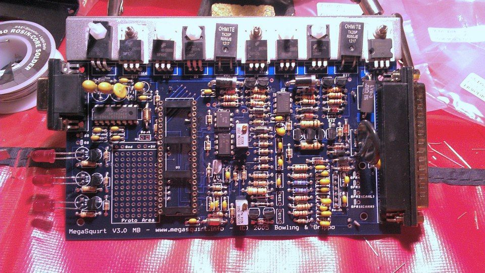
I get what you are saying. I've built a few of these MegaSquirt boards to fuel inject my old cars. One is on its 11th year and well over 100,000 miles, but I've seen LOTS of people give up on it too. Maybe its nostalgia, but there is some excitement about starting my next car hobby technology leap with the same board assembly starting point as I did about 12 years ago. Lego's for adults as I call it, lol. Admittedly though, just starting out in this, its pretty overwhelming, but so was going from carburetor to fuel injection 12 years ago.
The tuning software has improved a ton over the last 12 years. From ini file editing to running full GUI in Java now and piles of auto-tuning options.
The tuning software has improved a ton over the last 12 years. From ini file editing to running full GUI in Java now and piles of auto-tuning options.
Need to learn. Starting from the basics.
-
Isaac96
- Posts: 656
- Joined: Sat Oct 05, 2019 6:50 pm
- Location: Northern California, USA
- Been thanked: 1 time
- Contact:
Re: Introduction and a few basic questions.
11 years from a DIY board.... Amazing. I've heard about the MegaSquirts and thought about building one once, but got scared off by the general complexity (and not having a car to play with... oof)
Looks like you've got the experience and the abilities to more or less do as you please. Maybe take a gander at Johannes' schematics for the current sensor scaling (that might have only been an issue for the gen2, maybe gen3 is easier?).
-Isaac
Looks like you've got the experience and the abilities to more or less do as you please. Maybe take a gander at Johannes' schematics for the current sensor scaling (that might have only been an issue for the gen2, maybe gen3 is easier?).
-Isaac
-
TheSilverBuick
- Posts: 187
- Joined: Mon Jun 08, 2020 5:01 pm
- Location: Nevada, United States
- Has thanked: 3 times
- Been thanked: 1 time
Re: Introduction and a few basic questions.
Yeah, my first EFI conversion in 2008 was a simple GM throttle body injection setup I bolted on my '67 Thunderbird. Used a basic MS1 ecu. Car never started as easy as it did with that TBI, but I never got the throttle linkage geometry right and it was touchy off idle and would be at WOT at half pedal travel. But gave me the confidence to go full multiport EFI the following year on my Buick with a MS2 ecu that eventually was upgraded to a MS3. Following the same premise here. If the ATV conversion works, the '67 Thunderbird will get an EV overhaul.
Need to learn. Starting from the basics.
-
TheSilverBuick
- Posts: 187
- Joined: Mon Jun 08, 2020 5:01 pm
- Location: Nevada, United States
- Has thanked: 3 times
- Been thanked: 1 time
Re: Introduction and a few basic questions.
Picked up a Lexus/Toyota MGR for $100 today. Was supposed to be a 2012 unit, but when they brought it out it was missing the axle shafts that were in the advertisement, so they went back and found a less pretty 2006 one. At least the copper connectors are clear of corrosion and there is a 1 year warranty on it.
It definitely weighs less than the transmission I currently have removed and the potential ~68Hp should be nicer than the maybe peaky 20HP of the 2-stroke engine. At some point I'll need to start a project thread. $50 inverter, $100 MGR. Working on getting a through hole Damien board.
It definitely weighs less than the transmission I currently have removed and the potential ~68Hp should be nicer than the maybe peaky 20HP of the 2-stroke engine. At some point I'll need to start a project thread. $50 inverter, $100 MGR. Working on getting a through hole Damien board.
Need to learn. Starting from the basics.
-
TheSilverBuick
- Posts: 187
- Joined: Mon Jun 08, 2020 5:01 pm
- Location: Nevada, United States
- Has thanked: 3 times
- Been thanked: 1 time
Re: Introduction and a few basic questions.
Does this Toyota Prius "relay" setup do the job of the contactors and pre-charge relay? Or would I still need some contactors, like the Kilovac EV200's? I expect to have well under 200 volts worth of battery.

Need to learn. Starting from the basics.
-
muehlpower

- Posts: 574
- Joined: Fri Oct 11, 2019 10:51 am
- Location: Germany Fürstenfeldbruck
- Has thanked: 12 times
- Been thanked: 103 times
Re: Introduction and a few basic questions.
I think that was discussed on EV car conversion hardware on page 9
-
JaniK
- Posts: 391
- Joined: Sun Aug 25, 2019 12:39 pm
- Location: Finland
- Has thanked: 49 times
- Been thanked: 10 times
Re: Introduction and a few basic questions.
I feel envious for those mgr and inverter prices.. I could get same stuff home for about triple your price.
Any opinions are my own, unless stated otherwise. I take no responsibility if you follow my way of doing things and it doesn't work. Please double check with someone who knows what they are doing.
-
TheSilverBuick
- Posts: 187
- Joined: Mon Jun 08, 2020 5:01 pm
- Location: Nevada, United States
- Has thanked: 3 times
- Been thanked: 1 time
Re: Introduction and a few basic questions.
Thanks for the directionmuehlpower wrote: ↑Wed Jul 08, 2020 4:04 pm I think that was discussed on EV car conversion hardware on page 9
Need to learn. Starting from the basics.
-
TheSilverBuick
- Posts: 187
- Joined: Mon Jun 08, 2020 5:01 pm
- Location: Nevada, United States
- Has thanked: 3 times
- Been thanked: 1 time
Re: Introduction and a few basic questions.
Continuing on with my basic questions. I have an old evbmw.com Prius Gen2 inverter through hole control board on its way, and reading through the forum and wiki to see how to wire in the toyota MGR, I'm seeing two complications, one maybe a hangup?
The Toyota MGR uses a resolver, but from what I can tell the board itself does not have a resolver exciter on it? The wiki says "Functionality of the existing resolver is integrated as well." which I assume is the encoder inputs? But still requires something external to excite the resolver? Would this be a show stopper for using this basic board for this motor?
The other question is, under the FOC controls, it references current feed back as required for control, but the wiki shows the current inputs as "optional", which I'm sure it is for certain motors, but I am thinking for the Toyota MGR unit it would be required. Is this the circuit that needs to go from 5v down to 3.3v using a simple voltage divider circuit?
Thanks!
Need to learn. Starting from the basics.
-
konstantin8818

- Posts: 287
- Joined: Sun Jan 19, 2020 2:33 pm
- Location: Minsk, Belarus
- Been thanked: 5 times
Re: Introduction and a few basic questions.
AFAIK STM32 chip of Blue Pill is not sutible for FOC control, it lacks some pins. However there is an option, I can offer. Damien mistakenly(or notTheSilverBuick wrote: ↑Sat Jul 18, 2020 11:39 pm Continuing on with my basic questions. I have an old evbmw.com Prius Gen2 inverter through hole control board on its way, and reading through the forum and wiki to see how to wire in the toyota MGR, I'm seeing two complications, one maybe a hangup?
The Toyota MGR uses a resolver, but from what I can tell the board itself does not have a resolver exciter on it? The wiki says "Functionality of the existing resolver is integrated as well." which I assume is the encoder inputs? But still requires something external to excite the resolver? Would this be a show stopper for using this basic board for this motor?
The other question is, under the FOC controls, it references current feed back as required for control, but the wiki shows the current inputs as "optional", which I'm sure it is for certain motors, but I am thinking for the Toyota MGR unit it would be required. Is this the circuit that needs to go from 5v down to 3.3v using a simple voltage divider circuit?
Thanks!
Re: Introduction and a few basic questions.
According to:konstantin8818 wrote: ↑Sun Jul 19, 2020 7:13 am
AFAIK STM32 chip of Blue Pill is not sutible for FOC control, it lacks some pins. However there is an option, I can offer. Damien mistakenly(or not) sent me new unused Auris/Yaris board, and Auris/Yaris is "no go" here in Belarus, only one inverter is being sold online and it costs 400 euro
I'm definitely not going to buy it. It would be a shame if board will just lie on the shelf. Can send it to you, but all shipment expenses are on you.
viewtopic.php?f=3&t=220&start=20#p2623
viewtopic.php?f=14&t=228#p2664
Exciter pin exists on blue pill but the circuit is lacking from JB´s board? Shouldn't you be able to copy the circuit from github to a breadboard?
For the current sensor inputs a level shifter schematic was posted by SciroccoEV:
viewtopic.php?f=14&t=228&start=160#p9043
See kiwifiat´s remarks on resistor values and vref:
viewtopic.php?f=14&t=228&start=170#p9049
At least those two circuits need to be added for using FOC. I don´t have the board myself but do have MGR + Gen2 inverter combo.
-
TheSilverBuick
- Posts: 187
- Joined: Mon Jun 08, 2020 5:01 pm
- Location: Nevada, United States
- Has thanked: 3 times
- Been thanked: 1 time
Re: Introduction and a few basic questions.
Thank you for the responses, I've been looking it over and reading more. I've read through those before and its a case of "I didn't know what I was looking at" so didn't stick with me.
Two questions on the circuit posted by kiwifiat, what is the part number for U1? And what wattages are recommended? I would think lower if fine in this application, but not certain. It is also referenced later that C1's rating needs to go from 1nF to 100nF.
Two questions on the circuit posted by kiwifiat, what is the part number for U1? And what wattages are recommended? I would think lower if fine in this application, but not certain. It is also referenced later that C1's rating needs to go from 1nF to 100nF.
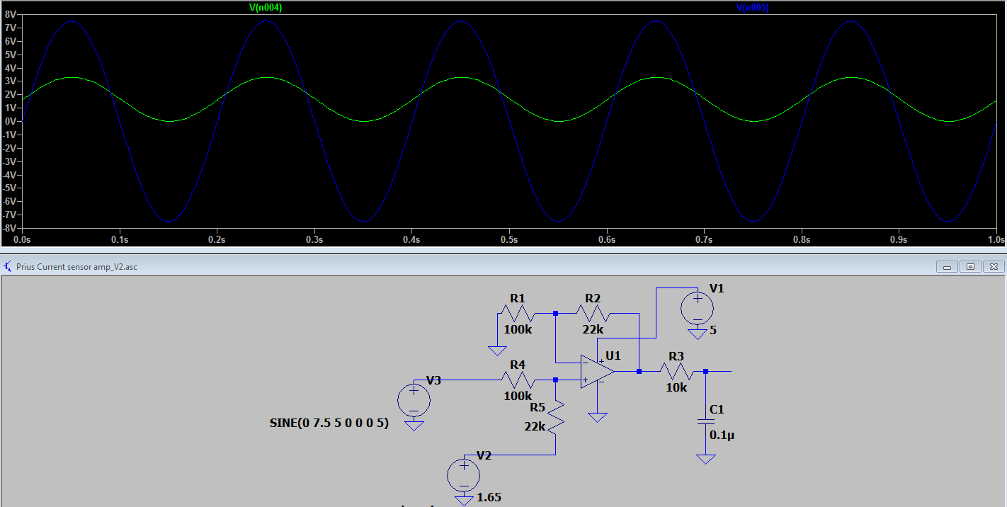
I'm not discouraged yet, but feeling daunted =P Now to find the information needed to make the exciter circuit.....kiwifiat wrote: ↑Thu Apr 16, 2020 4:16 pm The Prius Gen2 current sensors are bipolar 15Vp-p, not 10V or 7.1V. Use whatever you like as the 1.65V reference, what is critical is the OP amp output does not saturate as in the case of FOC accuracy of the current input is important to the control algorithm :
Need to learn. Starting from the basics.
Re: Introduction and a few basic questions.
Sorry, can't help with component values, but here is the schematic from johu's github:
Doesn't seem to be connected to any STM pin, wonder what that pin marked as "exciter" does on blue pill.. Anyway, maybe these posts would be better of under the appropriate thread.
-
Kevin Sharpe

- Posts: 1345
- Joined: Fri Dec 14, 2018 9:24 pm
- Location: Ireland and US
- Been thanked: 4 times
Re: 6x6 Max
I've moved this thread into 'projects' because 'general' is getting unmanageable
This is a personal post and I disclaim all responsibility for any loss or damage which any person may suffer from reliance on the information and material in this post or any opinion, conclusion or recommendation in the information and material.
-
kiwifiat
- Posts: 99
- Joined: Sat Dec 22, 2018 9:39 pm
- Location: Vancouver, Canada
- Been thanked: 10 times
Re: Introduction and a few basic questions.
The circuit TheSilverBuick posted is for level shifting the Prius current sensors so they are compatible with the ADC converters on the STM32.jap wrote: ↑Mon Jul 20, 2020 2:33 pm Sorry, can't help with component values, but here is the schematic from johu's github:
res.jpg
Doesn't seem to be connected to any STM pin, wonder what that pin marked as "exciter" does on blue pill.. Anyway, maybe these posts would be better of under the appropriate thread.
TheSilverBuick can you please clarify if you are trying to build a current sensor conditioner or a resolver driver?
-
TheSilverBuick
- Posts: 187
- Joined: Mon Jun 08, 2020 5:01 pm
- Location: Nevada, United States
- Has thanked: 3 times
- Been thanked: 1 time
Re: 6x6 Max
The answer is both.
The obsolete Damien blue pill board for the Gen2 Prius inverter did not have a resolver exciter circuit, and the two current inputs cannot take the Toyota outputs directly, so need to be conditioned.
The voltage divider circuit looks straight forward enough, but the resolver exciter/driver schematic looks daunting for my skill level. I'm mulling over attempting it versus simply purchasing a Yaris board for my other inverter.
Need to learn. Starting from the basics.
-
kiwifiat
- Posts: 99
- Joined: Sat Dec 22, 2018 9:39 pm
- Location: Vancouver, Canada
- Been thanked: 10 times
Re: 6x6 Max
Contact Arber333, he designed a board for the resolver exciter/driver and he may still have some bare boards for sale. Johu posted an updated variation that eliminated the voltage reference I used in my design for the current sensor conditioning. I would use his schematic.TheSilverBuick wrote: ↑Thu Jul 23, 2020 5:06 am The answer is both.
The obsolete Damien blue pill board for the Gen2 Prius inverter did not have a resolver exciter circuit, and the two current inputs cannot take the Toyota outputs directly, so need to be conditioned.
The voltage divider circuit looks straight forward enough, but the resolver exciter/driver schematic looks daunting for my skill level. I'm mulling over attempting it versus simply purchasing a Yaris board for my other inverter.
-
TheSilverBuick
- Posts: 187
- Joined: Mon Jun 08, 2020 5:01 pm
- Location: Nevada, United States
- Has thanked: 3 times
- Been thanked: 1 time
Re: 6x6 Max
So after some thought and more reading, I'm still going to try my hand at the blue pill board with the Gen2 prius inverter and toyota MGR.
I've made the order to Digikey for the parts, have an STM32 chip and programmer on the way. I got the Wifi chip a while back. Arber333 says he has one more exciter board, so working on getting it.
Now the remaining questions on the voltage divider for the two current sensors that I've bolded below. Thanks!
Side note, I've picked up a 30v PSU and dug out an old oscilloscope that I had stuck in a closet for ever. Waiting on some new leads to see if it still works.TheSilverBuick wrote: ↑Mon Jul 20, 2020 12:04 pm Two questions on the circuit posted by kiwifiat, what is the part number for U1? And what wattages are recommended? I would think lower if fine in this application, but not certain. It is also referenced later that C1's rating needs to go from 1nF to 100nF.
kiwifiat wrote: ↑Thu Apr 16, 2020 4:16 pm The Prius Gen2 current sensors are bipolar 15Vp-p, not 10V or 7.1V. Use whatever you like as the 1.65V reference, what is critical is the OP amp output does not saturate as in the case of FOC accuracy of the current input is important to the control algorithm :
Need to learn. Starting from the basics.