Search found 18 matches
- Sun Nov 19, 2023 9:53 am
- Forum: Hyundai/Kia
- Topic: Kia Niro BMS
- Replies: 146
- Views: 32124
Re: Kia Niro BMS
Could you tell about useable capacity when low limit is 3,2V per cell? In a fact I can test it by my charger, but when discharging relatively low current it won't be reliable. I think of buying battery for another project, but by budget about 1000 euros Outlander battery 12kWh seems to be better cho...
- Fri Nov 17, 2023 3:47 pm
- Forum: Hyundai/Kia
- Topic: Kia Niro BMS
- Replies: 146
- Views: 32124
Re: Kia Niro BMS
Do you know if 24,7Ah is total or netto capacity of this cells?
- Thu Mar 23, 2023 7:52 pm
- Forum: Inverters / Motor Controllers
- Topic: Toyota Invertor Gen2 Problem
- Replies: 24
- Views: 3139
Re: Toyota Invertor Gen2 Problem
I suppose that 1 and 4 should be connected to TEMP and TEMP- (but what polarity?). One of 2 and 3 should be powered by 12v and other connected to IN_MPROT. There is still issue what type of temp sensor should be chosen in inverter settings. In a fact I have got bigger trouble now, because I realised...
- Sun Mar 19, 2023 6:54 pm
- Forum: Inverters / Motor Controllers
- Topic: Toyota Invertor Gen2 Problem
- Replies: 24
- Views: 3139
Re: Toyota Invertor Gen2 Problem
Do someone know what kind of temp sensor is used in this motor? There are 4 pin, in original wiring pins 1 and 4 are twisted pair (10k between them), pins 2 and 3 are shorted.
- Sat Mar 18, 2023 8:29 am
- Forum: Mitsubishi
- Topic: Mitsubishi Outlander Front inverter
- Replies: 7
- Views: 4096
Re: Mitsubishi Outlander Front inverter
@nathaniel
I have a few questions, because I configuring the same setup - MB V3 and front inverter, but with another motor (SMG 180/120). Do you need still to cheat about a battery configuration (I will use 96s too)? How did you set a dead time value?
I have a few questions, because I configuring the same setup - MB V3 and front inverter, but with another motor (SMG 180/120). Do you need still to cheat about a battery configuration (I will use 96s too)? How did you set a dead time value?
- Tue Feb 28, 2023 10:24 pm
- Forum: Mitsubishi
- Topic: Outlander FEMCU (front inverter)
- Replies: 49
- Views: 15737
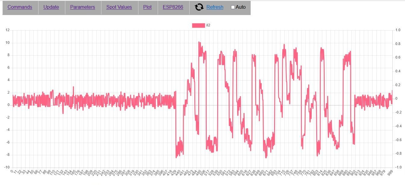
Re: Outlander FEMCU (front inverter)
I was trying to calibrate the current sensor with sinus load 9A (50Hz) and got such plot. Is it correct? I think that level of jitter (first there was no load) is too high, isn't it?
- Sat Jan 07, 2023 4:13 pm
- Forum: Inverters / Motor Controllers
- Topic: Toyota Invertor Gen2 Problem
- Replies: 24
- Views: 3139
Re: Toyota Invertor Gen2 Problem
Good news, so I can go further. It's my working pinout for resolver slot of Peugeot motor.
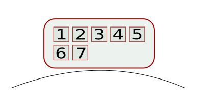
1 – Motor ground,
2 – EXC- → e.g. JP7 pin 16
3 – SIN- → JP2 pin 2
4 – SIN+ → JP2 pin 1
5 – COS- → JP2 pin 2
6 – COS+ → JP2 pin 3
7 – EXC → JP2 pin 4
1 – Motor ground,
2 – EXC- → e.g. JP7 pin 16
3 – SIN- → JP2 pin 2
4 – SIN+ → JP2 pin 1
5 – COS- → JP2 pin 2
6 – COS+ → JP2 pin 3
7 – EXC → JP2 pin 4
- Fri Jan 06, 2023 5:36 pm
- Forum: Inverters / Motor Controllers
- Topic: Toyota Invertor Gen2 Problem
- Replies: 24
- Views: 3139
Re: Toyota Invertor Gen2 Problem
I have the same motor. Could you confirm guys that it's correct resolver output? On Damien's film plot was more repeatable and regular, but maybe number of poles makes difference. https://images2.imgbox.com/ba/10/tU6vrkHy_o.jpg https://images2.imgbox.com/94/d7/1Gm2Beqb_o.jpg https://images2.imgbox.c...
- Sun Nov 13, 2022 9:08 am
- Forum: Getting Started
- Topic: Excitation output problem
- Replies: 7
- Views: 650
Re: Excitation output problem
I haven't got oscilloscope yet, I'll get it tomorrow, so I measured using simply multimeter. Between pin 4 and GND there is 5,4 kHz frequency and 3,3 V on AC range. It seems I was doing something wrong while previous tests, mayby I measured voltage on DC range. Will it be ok if excitation of my reso...
- Sat Nov 12, 2022 8:50 pm
- Forum: Getting Started
- Topic: Excitation output problem
- Replies: 7
- Views: 650
Re: Excitation output problem
Ok, it works. I expected some voltage on pin 4 and on sin/cos, but I can"t measure any. However there was wave 4,4kHz on R40 and about 5kHz on pin 4. I connected sin/cos wires and get some feedback. Does it mean, that sin/cos voltage can be measured only by oscilloscope?
- Sat Nov 12, 2022 6:31 pm
- Forum: Getting Started
- Topic: Excitation output problem
- Replies: 7
- Views: 650
Re: Excitation output problem
Thanks, it helped enter ManualRun, but there is still status "EmcyStop" and no live on pin 4. Should I connect pin 17 to 12V too?
- Sat Nov 12, 2022 4:05 pm
- Forum: Getting Started
- Topic: Excitation output problem
- Replies: 7
- Views: 650
Excitation output problem
Hello. I was trying test sin/cos output voltage to make properly resistor devider for MB v.3, but get stuck because there is no any voltage on pin 4 (excitation). I switched firmware to 4.97, as in instruction for FOC tuning, but "opmode" is still "Off" and "staus" says...
- Tue Nov 01, 2022 7:45 pm
- Forum: Mitsubishi
- Topic: Outlander FEMCU (front inverter)
- Replies: 49
- Views: 15737
Re: Outlander FEMCU (front inverter)
Hello @jamesn. Could you please share details about connecting Johannes board v3 to FEMCU? I'll try it despite yours experiences. I'm using Bosch SMG 180/120, maybe it will be easier.
- Sun Sep 18, 2022 5:39 pm
- Forum: Hyundai/Kia
- Topic: Kia Niro BMS
- Replies: 146
- Views: 32124
Re: Kia Niro BMS
Thank You. Unfortunately I must look for this current sensor or similar, because in my pack ("underseats" only) there wasn't any.
- Sun Sep 18, 2022 3:06 pm
- Forum: Hyundai/Kia
- Topic: Kia Niro BMS
- Replies: 146
- Views: 32124
Re: Kia Niro BMS
Hello @bexander. Could You share the code for ATtiny85? And another question - what type of current sensor (for A6 and A7) do You use?
- Sun Jul 24, 2022 6:20 pm
- Forum: Hyundai/Kia
- Topic: Kia Niro BMS
- Replies: 146
- Views: 32124
Re: Kia Niro BMS
Thanks a lot, it's very helpful. Probably I'll have a few questions, so be patient, please  Now I must check availability of some electronic components in Poland, and then track PCB in THT, because I have't experience in SMD. In programming too, so maybe it's good opportunity to learn.
- Sat Jul 23, 2022 10:29 pm
- Forum: Hyundai/Kia
- Topic: Kia Niro BMS
- Replies: 146
- Views: 32124
Re: Kia Niro BMS
You did great job with this BMS. I have the same battery pack (half of them, in a fact, under seats only), so I'm very interested in your idea. I can see the code is more complicated now and there are changes to the schema. Could you tell us more about the current PCB version?
- Wed Jul 20, 2022 4:37 pm
- Forum: Getting Started
- Topic: Main board V3 - input/output signal voltage conversion
- Replies: 0
- Views: 454
Main board V3 - input/output signal voltage conversion
Hello. I'm trying to do inverter for my Seat Arosa using main board V3 nad OEM Kia Niro hybrid inverter. Input (PWM) and output (fault signal for every phase) voltage for my IGBT driver board is 5V. Is it good and reliable solution usage of cheap chinese 3,3V to 5V converter (Level Shifter Module), ...